Transit-Time Ultrasonic

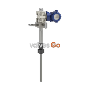
Yoshitake ODF-100 series orifice flowmeter for saturated steam. Features differential pressure measurement, multi-function transmitter, HART communication, and wafer connection JIS10K.
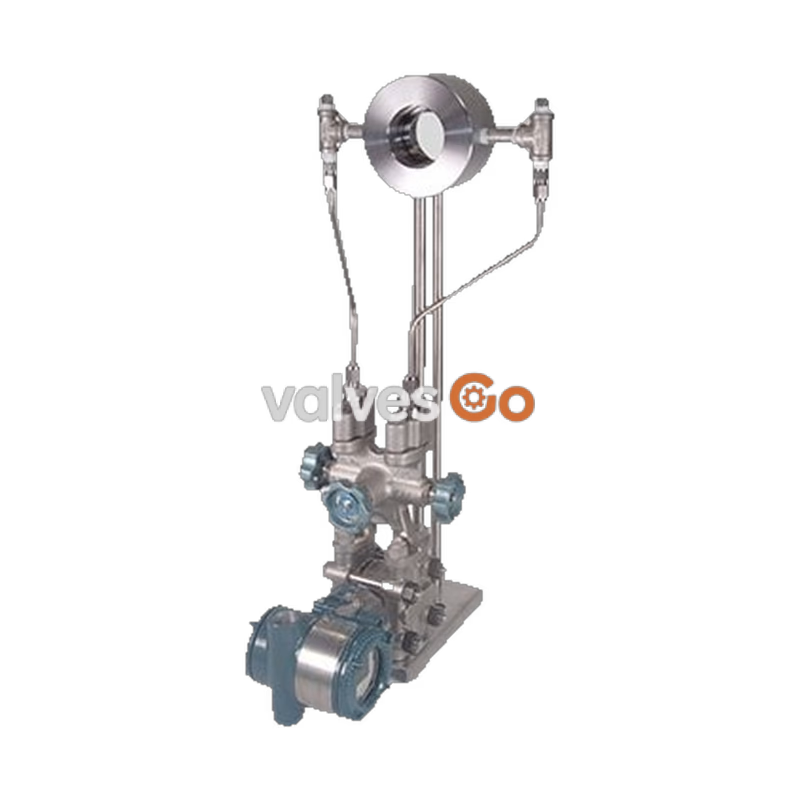
The Yoshitake ODF-100 series is an orifice flowmeter for steam (differential pressure type) that can measure flow rates using a multi-function transmitter. It operates on the principle that the square root of the differential pressure generated before and after the orifice is proportional to the flow rate. The ODF-100 is less subject to drain and vibration, offers fast response speeds, and is suitable for a wide range of steam conditions.
Typical applications include steam flowrate measurement of various devices, measurement pertaining to the sale of commodities for purchased steam, steam flow measurement in sterilization processes, steam flow measurement of air conditioning systems, and flow control by combination with a control valve.
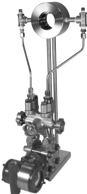
| Specification | Value |
|---|---|
| Model | ODF-100 |
| Application | Saturated steam |
| Nominal size | 15A ~ 200A |
| Connection | Wafer connection JIS10K |
| Maximum working pressure | 1.0MPa |
| Maximum working temperature | 220°C (Heat resistant temperature of differential pressure gauge is -40°C to 120°C, and no freezing) |
| Working temperature | -30°C ~ 80°C |
| Degree of protection | IP67 |
| Built-in indicator | LCD digital indicator (Instantaneous flow rate, integrated flow rate, static pressure, etc.) |
| Flow direction | Horizontal / Vertical |
| Power supply voltage | 10.5 ~ 42V DC (Power connection port G1/2 female thread) |
| Output | 4-20mA, Pulse |
| Communication | Hart |
| Required straight pipe length | Normally piping: upstream 10D, downstream 5D (D stands for caliber diameter). Upstream and downstream can be used on 8D and 5D by combination with a rectifier. |
Static pressure, differential pressure, and temperature can be measured by adopting a multifunctional transmitter. Based on the built-in steam table, a wide range of conditions can be accurately measured with a mass flow calculation function.
The integrated structure with the differential pressure gauge eliminates the need for impulse pipe construction, making it easy to install the flowmeter and contributing to space savings.
Available on left to right, right to left, top to bottom, and bottom to top flow directions. Please specify the flow direction when ordering.
HART communication allows you to manage the parameters of the transmitter and check the flow rate status remotely. Software and equipment are required separately.
Feasible low-pressure loss by designing the differential pressure and throttle diameter according to the measured flow rate.
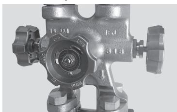
Equipped with a three-way valve that integrates a stop valve (high pressure side, low pressure side) and a pressure equalizing valve (high pressure side and low pressure side bypass), enabling maintenance work without stopping the steam process.
Error is smaller than a vortex flowmeter due to measurement using differential pressure, and the response speed is fast.
Surveillance monitoring, data accumulation, and trend analysis are possible by combining with a Wi-Flo system.

Because of the wafer connection structure, centering is achieved by flange bolts simply by sandwiching between connection flanges.
The built-in LCD digital indicator can alternately display up to 4 process values: instantaneous flow rate value, integrated flow rate value, static pressure, differential pressure, bar graph, etc.
The orifice measurement part has no moving parts and is hard to break, making it ideal for lines that repeat ON/OFF action.
Flow control is possible by combining with a control valve.

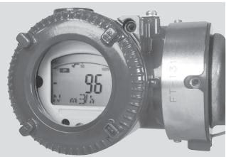
※ Flow unit is kg/h for steam.
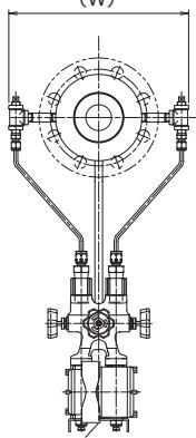
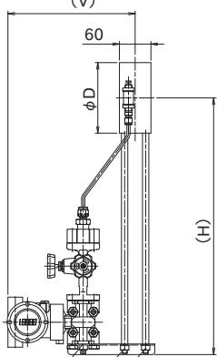
| Size (Bore Size) | D | V | W | H | Weight (kg) |
|---|---|---|---|---|---|
| 15A JIS10K | 58 | 243 | 204 | 452 | 16 |
| 20A JIS10K | 63 | 243 | 209 | 455 | 16 |
| 25A JIS10K | 74 | 243 | 220 | 460 | 16 |
| 32A JIS10K | 84 | 243 | 230 | 465 | 18 |
| 40A JIS10K | 89 | 243 | 235 | 468 | 18 |
| 50A JIS10K | 104 | 243 | 250 | 475 | 19 |
| 65A JIS10K | 124 | 243 | 270 | 485 | 21 |
| 80A JIS10K | 134 | 243 | 280 | 490 | 22 |
| 100A JIS10K | 159 | 243 | 305 | 503 | 25 |
| 125A JIS10K | 190 | 243 | 336 | 518 | 31 |
| 150A JIS10K | 220 | 243 | 366 | 533 | 35 |
| 200A JIS10K | 270 | 243 | 416 | 558 | 41 |
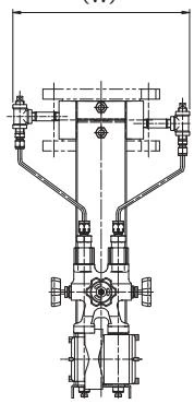

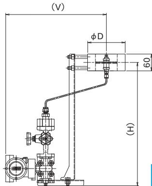
| Size (Bore Size) | D | V | W | H | Weight (kg) |
|---|---|---|---|---|---|
| 15A JIS10K | 58 | 302 | 204 | 440 | 17 |
| 20A JIS10K | 63 | 305 | 209 | 440 | 17 |
| 25A JIS10K | 74 | 310 | 220 | 440 | 18 |
| 32A JIS10K | 84 | 315 | 230 | 440 | 19 |
| 40A JIS10K | 89 | 318 | 235 | 440 | 19 |
| 50A JIS10K | 104 | 325 | 250 | 440 | 21 |
| 65A JIS10K | 124 | 335 | 270 | 440 | 22 |
| 80A JIS10K | 134 | 340 | 280 | 440 | 23 |
| 100A JIS10K | 159 | 353 | 305 | 440 | 27 |
| 125A JIS10K | 190 | 368 | 336 | 440 | 32 |
| 150A JIS10K | 220 | 383 | 366 | 440 | 36 |
| 200A JIS10K | 270 | 408 | 416 | 440 | 42 |
Installation Notes
Upstream and downstream can be used on 8D and 5D by combination with a rectifier.
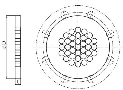
| Size (Bore Size) | D | t | Size (Bore Size) | D | t |
|---|---|---|---|---|---|
| 15A JIS10K | 58 | 7.0 | 65A JIS10K | 124 | 8.6 |
| 20A JIS10K | 63 | 7.0 | 80A JIS10K | 134 | 10.2 |
| 25A JIS10K | 74 | 7.0 | 100A JIS10K | 159 | 13.3 |
| 32A JIS10K | 84 | 7.0 | 125A JIS10K | 190 | 16.5 |
| 40A JIS10K | 89 | 7.0 | 150A JIS10K | 220 | 19.6 |
| 50A JIS10K | 104 | 7.0 | 200A JIS10K | 270 | 26.0 |
Three flow ranges are available: standard flow for general piping, large flow for upstream on main pipe use, and small flow for downstream equipment. (Units: kg/h)
(Flow Velocity Max. 30m/s, Differential Pressure 50kPa, Measurement Range 10:1)
| Working Pressure (MPa) | 0.1 | 0.2 | 0.3 | 0.4 | 0.5 | 0.6 | 0.7 | 0.8 | 0.9 | 1.0 |
|---|---|---|---|---|---|---|---|---|---|---|
| 15A | 55 | 66 | 76 | 84 | 91 | 98 | 105 | 111 | 117 | 122 |
| 20A | 99 | 119 | 136 | 152 | 165 | 177 | 189 | 200 | 210 | 220 |
| 25A | 161 | 195 | 223 | 248 | 270 | 290 | 309 | 327 | 344 | 360 |
| 32A | 270 | 327 | 374 | 415 | 452 | 486 | 518 | 548 | 576 | 603 |
| 40A | 367 | 444 | 508 | 564 | 614 | 661 | 704 | 744 | 783 | 819 |
| 50A | 594 | 718 | 822 | 912 | 993 | 1,069 | 1,139 | 1,204 | 1,266 | 1,325 |
| 65A | 978 | 1,183 | 1,354 | 1,503 | 1,637 | 1,761 | 1,876 | 1,984 | 2,086 | 2,183 |
| 80A | 1,382 | 1,671 | 1,912 | 2,123 | 2,311 | 2,487 | 2,649 | 2,802 | 2,946 | 3,083 |
| 100A | 2,353 | 2,845 | 3,257 | 3,615 | 3,936 | 4,235 | 4,511 | 4,771 | 5,016 | 5,250 |
| 125A | 3,631 | 4,390 | 5,025 | 5,579 | 6,074 | 6,535 | 6,961 | 7,362 | 7,741 | 8,101 |
| 150A | 5,112 | 6,181 | 7,075 | 7,855 | 8,551 | 9,202 | 9,801 | 10,365 | 10,899 | 11,406 |
| 200A | 8,893 | 10,753 | 12,308 | 13,664 | 14,876 | 16,007 | 17,050 | 18,032 | 18,959 | 19,842 |
(Flow Velocity Max. 15m/s, Differential Pressure 50kPa, Measurement Range 10:1)
| Working Pressure (MPa) | 0.1 | 0.2 | 0.3 | 0.4 | 0.5 | 0.6 | 0.7 | 0.8 | 0.9 | 1.0 |
|---|---|---|---|---|---|---|---|---|---|---|
| 15A | 27 | 33 | 38 | 42 | 46 | 49 | 52 | 55 | 58 | 61 |
| 20A | 49 | 60 | 68 | 76 | 82 | 89 | 95 | 100 | 105 | 110 |
| 25A | 81 | 98 | 112 | 124 | 135 | 145 | 155 | 164 | 172 | 180 |
| 32A | 135 | 163 | 187 | 208 | 226 | 243 | 259 | 274 | 288 | 302 |
| 40A | 184 | 222 | 254 | 282 | 307 | 330 | 352 | 372 | 391 | 410 |
| 50A | 297 | 359 | 411 | 456 | 497 | 534 | 569 | 602 | 633 | 663 |
| 65A | 489 | 592 | 677 | 752 | 818 | 881 | 938 | 992 | 1,043 | 1,092 |
| 80A | 691 | 835 | 956 | 1,062 | 1,156 | 1,244 | 1,325 | 1,401 | 1,473 | 1,542 |
| 100A | 1,177 | 1,423 | 1,628 | 1,808 | 1,968 | 2,118 | 2,256 | 2,386 | 2,508 | 2,625 |
| 125A | 1,815 | 2,195 | 2,513 | 2,789 | 3,037 | 3,268 | 3,480 | 3,681 | 3,870 | 4,051 |
| 150A | 2,556 | 3,091 | 3,538 | 3,927 | 4,276 | 4,601 | 4,900 | 5,183 | 5,449 | 5,703 |
| 200A | 4,447 | 5,377 | 6,154 | 6,832 | 7,438 | 8,004 | 8,525 | 9,016 | 9,480 | 9,921 |
(Flow Velocity Max. 15m/s, Differential Pressure 50kPa, Measurement Range 10:1)
| Working Pressure (MPa) | 0.1 | 0.2 | 0.3 | 0.4 | 0.5 | 0.6 | 0.7 | 0.8 | 0.9 | 1.0 |
|---|---|---|---|---|---|---|---|---|---|---|
| 15A | 82 | 99 | 114 | 126 | 137 | 148 | 157 | 166 | 175 | 183 |
| 20A | 148 | 179 | 205 | 227 | 247 | 266 | 284 | 300 | 315 | 330 |
| 25A | 242 | 293 | 335 | 372 | 405 | 436 | 464 | 491 | 516 | 540 |
| 32A | 405 | 490 | 561 | 623 | 678 | 730 | 777 | 822 | 864 | 905 |
| 40A | 551 | 666 | 762 | 846 | 921 | 991 | 1,056 | 1,116 | 1,174 | 1,229 |
| 50A | 891 | 1,077 | 1,233 | 1,369 | 1,490 | 1,603 | 1,708 | 1,806 | 1,899 | 1,988 |
| 65A | 1,468 | 1,775 | 2,031 | 2,255 | 2,455 | 2,642 | 2,814 | 2,976 | 3,129 | 3,275 |
| 80A | 2,073 | 2,506 | 2,869 | 3,185 | 3,467 | 3,731 | 3,974 | 4,203 | 4,419 | 4,625 |
| 100A | 3,530 | 4,268 | 4,885 | 5,423 | 5,904 | 6,353 | 6,767 | 7,157 | 7,525 | 7,875 |
| 125A | 5,446 | 6,586 | 7,538 | 8,368 | 9,110 | 9,803 | 10,441 | 11,043 | 11,611 | 12,152 |
| 150A | 7,668 | 9,272 | 10,613 | 11,782 | 12,827 | 13,803 | 14,701 | 15,548 | 16,348 | 17,109 |
| 200A | 13,340 | 16,130 | 18,462 | 20,496 | 22,314 | 24,011 | 25,575 | 27,048 | 28,452 | 29,788 |
Yoshitake Instrumentation / Flowmeters
ODF and UFM series flowmeters for on-site monitoring of steam, water, and other fluids.
Explore similar products in our catalog