Feed-Forward Design

Yoshitake GD-21 direct type differential pressure regulating valve for cold and hot water. Features ductile cast iron body, NBR diaphragm, and 0.05-0.7 MPa set pressure.
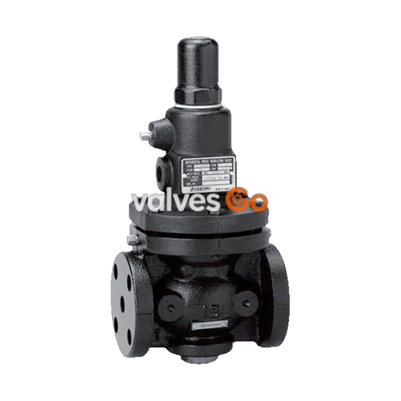
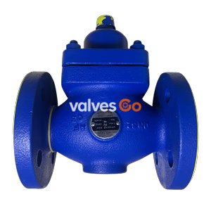
Yoshitake GD-21 is a direct type, diaphragm-operated differential pressure regulating valve designed for cold and hot water applications. It is highly suitable for use as a relief valve for pumps in closed circuits. Featuring a single seat valve and valve disc, the GD-21 ensures no leakage when closed. The valve features a ductile cast iron body and operates within a temperature range of 5 to 80°C.
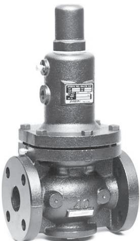
| Application | Cold and hot water |
|---|---|
| Regulating differential pressure | 15A-80A: (A) 0.05-0.25 MPa, (B) 0.26-0.7 MPa 100A-150A: (A) 0.05-0.25 MPa, (B) 0.26-0.5 MPa |
| Fluid temperature | 5-80°C |
| Material (Body) | Ductile cast iron |
| Material (Valve seat) | Stainless steel or bronze |
| Material (Valve disc) | NBR |
| Material (Diaphragm) | NBR |
| Connection | JIS 10K FF flanged |
| Inside surface treatment of body | 15A-100A: Electrodeposition coating 125A-150A: Tar-based coating (black) or Electrodeposition coating |
Caution
Please confirm that the indications on the product correspond with the specifications of the ordered model before use. If they are different, do not use the product and contact us.
| Nominal size | L | H | $H_1$ | d | Weight |
|---|---|---|---|---|---|
| 15A | 145 | 298 | 57 | 36 | 8.3 |
| 20A | 150 | 298 | 57 | 36 | 8.3 |
| 25A | 150 | 320 | 67 | 36 | 10.1 |
| 32A | 195 | 400 | 76 | 48 | 17.4 |
| 40A | 195 | 400 | 76 | 48 | 17.4 |
| 50A | 195 | 414 | 81 | 48 | 19.3 |
| 65A | 270 | 572 | 110 | 63 | 40.1 |
| 80A | 270 | 597 | 125 | 63 | 43.8 |
| 100A | 308 | 665 | 143 | 68 | 70.1 |
| 125A | 380 | 874 | 179 | 115 | 144.1 |
| 150A | 400 | 929 | 204 | 115 | 173.1 |
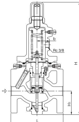
The material shapes are slightly different depending on the nominal size.
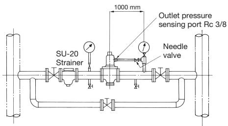
TIP
Install a needle valve to the outlet side of the product and plumb it to the pressure sensing pipe using copper piping.
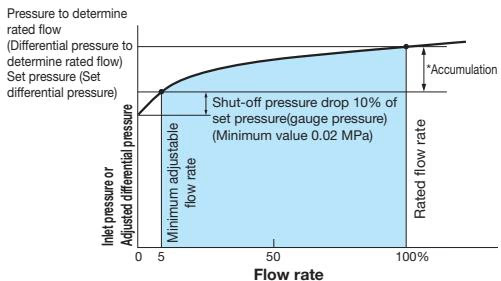
| Set range MPa | Accumulation MPa |
|---|---|
| 0.05-0.25 | Within 0.05 |
| 0.26-0.7 | Within 0.105 |
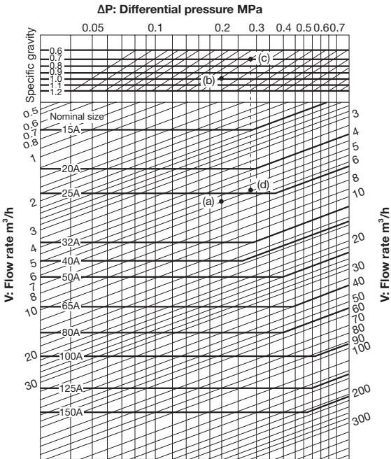
Example: When selecting the nominal size of a differential pressure regulating valve whose differential pressure (ΔP), specific gravity, and flow rate (V) are 0.2 MPa, 1 (water), and 5.5 m³/h, respectively, first trace down vertically from the differential pressure (ΔP) of 0.2 MPa to find intersection point (a) with the flow rate (V) of 5.5 m³/h. Since this intersection point (a) lies between nominal sizes 25A and 32A, select the larger one, 32A.
When the specific gravity is 0.7 under the same conditions, trace down vertically from the differential pressure (ΔP) of 0.2 MPa to find intersection point (b) with the specific gravity 1. Find intersection point (c) with the specific gravity of 0.7 by tracing horizontally to the slant lines from this intersection point (b). Then, find intersection point (d) with the flow rate (V) of 5.5 m³/h by tracing down vertically from intersection point (c). Since this intersection point (d) lies between nominal sizes 20A and 25A, select the larger one, 25A.
| Nominal size | 15A | 20A | 25A | 32A | 40A | 50A | 65A | 80A | 100A | 125A | 150A |
|---|---|---|---|---|---|---|---|---|---|---|---|
| Cv value | 1.5 | 2.7 | 4 | 8.5 | 11 | 14 | 23 | 32.5 | 48 | 75 | 108 |
$$ \mathbf {C v} = \frac {\mathbf {0 . 3 6 5 V} \sqrt {\mathbf {G}}}{\sqrt {\Delta \mathbf {P}}} $$
INFO
(1) Joint for the outlet pressure sensing is not included with the product package. (2) Secure the required space for maintenance and inspection.
Caution
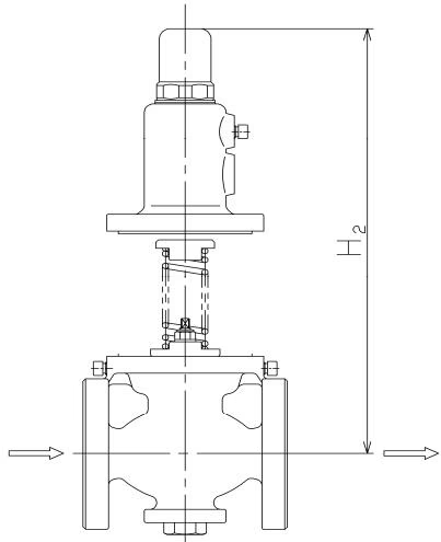
Space Required for Disassembly (mm)
| Nominal size | 15A | 20A | 25A | 32A | 40A | 50A | 65A | 80A | 100A | 125A | 150A |
|---|---|---|---|---|---|---|---|---|---|---|---|
| $H_2$ | 500 | 500 | 500 | 650 | 650 | 650 | 800 | 800 | 1000 | 1200 | 1400 |
Caution
Warning
Do not stand in front of the air vent valve during use. Failure to follow this notice may result in scalds or bodily injury due to blow-off of the fluid inside.
Caution
Do not rotate the air vents more than 1/2 turn when use. Failure to follow this notice may make the air vents detached from the body. In this case, the air vents may not be reattached.
How to Use Air Vent
Warning
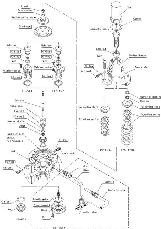
Nominal size 15-50A To remove the retainer guide easily, reattach the spring plate and U nut to the spindle, then pull up the spring plate. 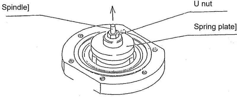
Nominal size 65-150A To remove the retainer guide easily, screw the bolt to the retainer guide and pull them out. 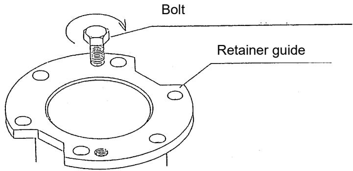
To reassemble the product, take reverse procedure to disassembly.
Caution
| Trouble | Cause | Remedy |
|---|---|---|
| Excessive leakage Adjustment is impossible. | 1. Foreign substances stuck between valve and valve seat. Or damage on valve and/or valve seat. 2. Damage on diaphragm and/or O-ring. 3. Nominal size is too small for the specifications. 4. Pressure gauge is out of order. | 1. Disassemble and clean, or replace. 2. Replace diaphragm and/or O-ring. 3. Replace the product to obtain proper nominal size. 4. Replace. |
| Abnormal sound is observed | 1. Air-induced problem occurs. 2. Nominal size is too large for the specifications. | 1. Install exhaust equipment. 2. Replace the product to obtain proper nominal size. |
Yoshitake Control Valves / Self-operated Regulators
OB, GPR, CF, and GD series self-operated regulators for pressure and temperature control without external power.
Explore similar products in our catalog