Lift Type

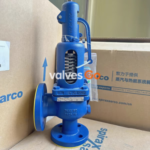
Yoshitake AL-400TL closed type lever safety relief valve for air, water, oil, and non-dangerous fluids. Features FCD450 body, stainless steel/PTFE trim, and JIS flanged connection for 0.05-1.3 MPa.
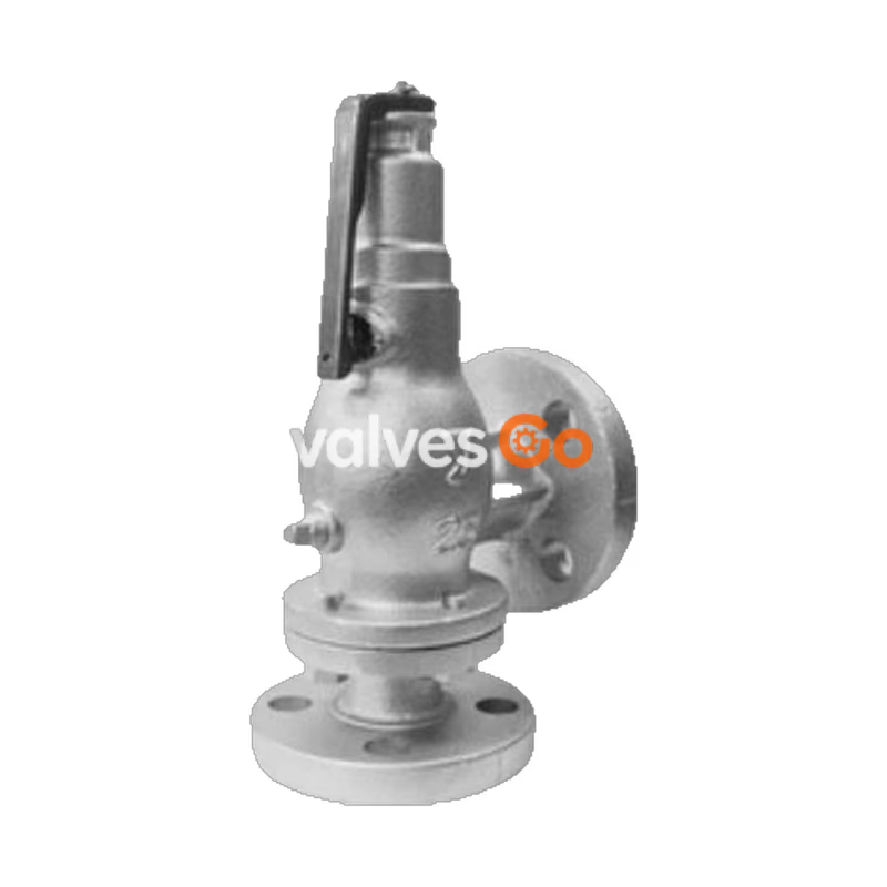
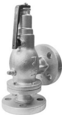
Yoshitake AL-400TL is a closed-type lever safety relief valve typically used on the outlet side of pressure reducing valves or small pressure vessels. Designed for air, water, oil, and other non-dangerous fluids, it features a ductile cast iron (FCD450) body with stainless steel and PTFE trim. The valve operates within a pressure range of 0.05 to 1.3 MPa and a maximum temperature of 120°C, providing a reliable discharge mechanism when predetermined opening pressures are reached.
| Model | AL-400L | AL-400TL |
|---|---|---|
| Structure | Open type with lever | Closed type with lever |
| Application fluid | Steam | Air, water, oil and other non-dangerous fluids |
| Maximum pressure | 0.05~1.6 MPa | 0.05~1.3 MPa |
| Maximum temperature | 220°C | 120°C |
| Connection | JIS 10K FF flanged / JIS 16K FF flanged* | JIS 10K FF flanged / JIS 16K FF flanged* |
| Valve case, spring case | Ductile cast iron (FCD450) | Ductile cast iron (FCD450) |
| Valve, valve seat | Stainless steel | Stainless steel • PTFE |
*JIS 16K FF flanges are used when the applicable pressure exceeds 1.0 MPa.
WARNING
(1) Do not use this product for equipment or devices that do not allow valve seat leakage. This product has valve seat leakage within the allowable value and cannot be completely closed. (2) This product cannot be used for equipment or devices that generate excessive vibration. (3) The set pressure cannot be adjusted (changed). (4) For applicable fluids, adhesive fluids that can cause the bonding of the valve and valve seat cannot be used.
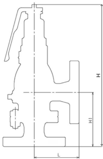
| Nominal size | L (mm) | H1 (mm) | H (mm) | Weight (kg) |
|---|---|---|---|---|
| 15A | 90 | 108 | 282 | 5.4 |
| 20A | 90 | 108 | 282 | 5.7 |
| 25A | 90 | 108 | 282 | 6.9 |
| 32A | 91 | 115 | 325 | 9.6 |
| 40A | 91 | 115 | 325 | 9.8 |
| 50A | 105 | 132 | 351 | 13.6 |
Unit: kg/h
| Nominal size \ Pressure MPa | 0.05 | 0.1 | 0.2 | 0.3 | 0.4 | 0.5 | 0.6 | 0.7 | 0.8 | 0.9 | 1.0 | 1.1 | 1.2 | 1.3 |
|---|---|---|---|---|---|---|---|---|---|---|---|---|---|---|
| 15A | 84 | 109 | 159 | 213 | 268 | 322 | 377 | 432 | 486 | 541 | 595 | 650 | 704 | 759 |
| 20A | 84 | 109 | 159 | 213 | 268 | 322 | 377 | 432 | 786 | 541 | 595 | 650 | 704 | 759 |
| 25A | 84 | 109 | 159 | 213 | 268 | 322 | 377 | 432 | 486 | 541 | 595 | 650 | 704 | 759 |
| 32A | 136 | 178 | 259 | 347 | 436 | 525 | 614 | 703 | 792 | 880 | 969 | 1058 | 1147 | 1236 |
| 40A | 136 | 178 | 259 | 347 | 436 | 525 | 614 | 703 | 792 | 880 | 969 | 1058 | 1147 | 1236 |
| 50A | 249 | 325 | 473 | 635 | 797 | 959 | 1121 | 1283 | 1445 | 1607 | 1769 | 1932 | 2094 | 2256 |
Unit: m³/h
| Nominal size \ Pressure MPa | 0.05 | 0.1 | 0.2 | 0.3 | 0.4 | 0.5 | 0.6 | 0.7 | 0.8 | 0.9 | 1.0 | 1.1 | 1.2 | 1.3 |
|---|---|---|---|---|---|---|---|---|---|---|---|---|---|---|
| 15A | 0.8 | 1.1 | 1.6 | 2.0 | 2.3 | 2.6 | 2.8 | 3.1 | 3.3 | 3.5 | 3.7 | 3.9 | 4.0 | 4.2 |
| 20A | 0.8 | 1.1 | 1.6 | 2.0 | 2.3 | 2.6 | 2.8 | 3.1 | 3.3 | 3.5 | 3.7 | 3.9 | 4.0 | 4.2 |
| 25A | 0.8 | 1.1 | 1.6 | 2.0 | 2.3 | 2.6 | 2.8 | 3.1 | 3.3 | 3.5 | 3.7 | 3.9 | 4.0 | 4.2 |
| 32A | 1.3 | 1.9 | 2.7 | 3.3 | 3.8 | 4.2 | 4.7 | 5.5 | 5.4 | 5.7 | 6.0 | 6.3 | 6.6 | 6.9 |
| 40A | 1.3 | 1.9 | 2.7 | 3.3 | 3.8 | 4.2 | 4.7 | 5.5 | 5.4 | 5.7 | 6.0 | 6.3 | 6.6 | 6.9 |
| 50A | 2.4 | 3.5 | 4.9 | 6.0 | 7.0 | 7.8 | 8.5 | 9.2 | 9.9 | 10.5 | 11.0 | 11.6 | 12.1 | 12.6 |
| No. | Name of Parts | Material |
|---|---|---|
| 1 | Spring Case | Ductile Cast Iron (FCD450) |
| 2 | Body | Ductile Cast Iron (FCD450) |
| 3 | Valve Seat | Stainless Steel (SUS304) |
| 4 | Valve / Valve · P | Stainless Steel & PTFE (SUS304 & PTFE etc) |
| 7 | Spring | Piano Wire or Steel Wire |
| 8 | Cap | Bronze (CAC406) |
| 14 | Name Plate | Aluminium |
| 17 | Lever | Stainless Steel (SUS430) |
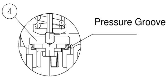
When the pressure at the inlet side of the safety relief valve is lower than the opening pressure, the valve / valve · P are held down by spring force and the valve is closed.
When the pressure on the inlet side increases and approaches the opening pressure, the force of the fluid trying to push up the valve approaches the force holding it down, causing it to start discharging. This gradual buildup of pressure in the pressure groove causes a vigorous popping operation when the predetermined opening pressure is reached.
When the valve is popped and fluid is released, the pressure on the inlet side decreases, and the force of the spring prevails, closing the valve.
DANGER
TIP
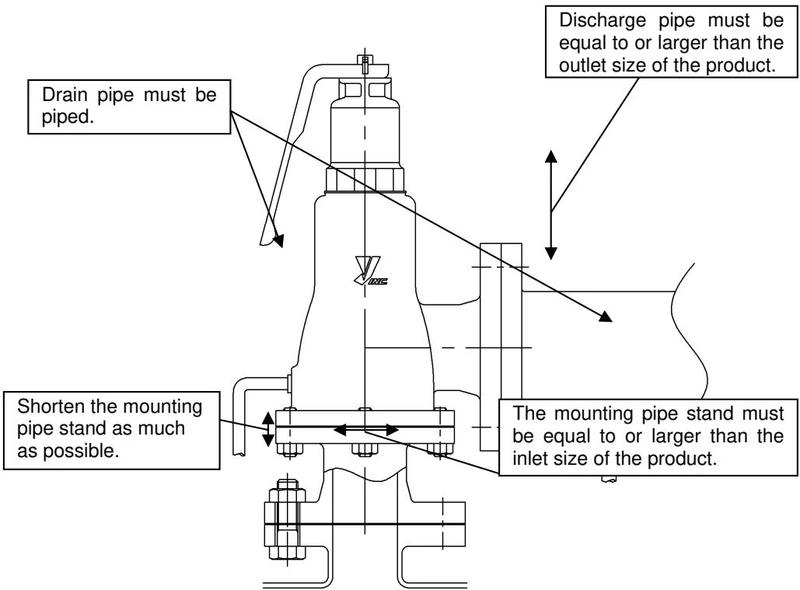
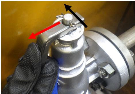
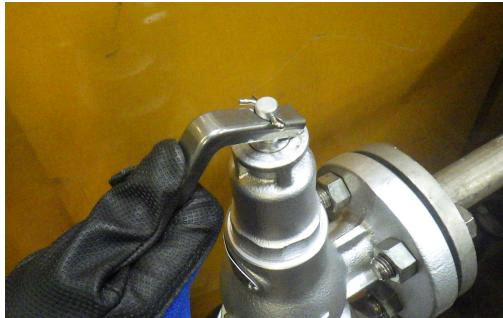
Increase the fluid pressure to 75% or more of the set pressure, lift the lever, and confirm that discharge occurs.
Lever Lifting Procedure:
Yoshitake Safety Valves / Relief Valves
AF and AL series safety and relief valves for overpressure protection of steam, water, and air equipment.
Explore similar products in our catalog