Lift Type

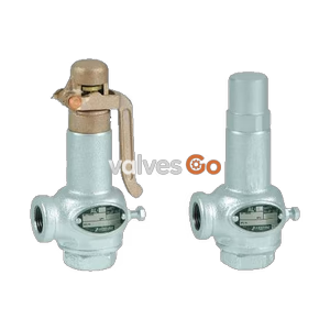
Yoshitake AL-400L and AL-400TL lever type safety relief valves for steam, air, water, and non-dangerous fluids. Features FCD450 body and JIS flanged connection.
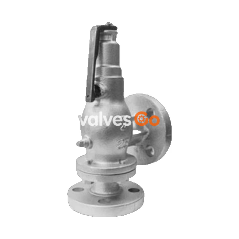
The Yoshitake AL-400L and AL-400TL are lever-type safety relief valves typically used on the outlet side of pressure reducing valves or small pressure vessels. The AL-400L is an open type designed for steam applications, while the AL-400TL is a closed type suitable for air, water, oil, and other non-dangerous fluids. Both models feature a durable ductile cast iron (FCD450) body and stainless steel trim for reliable performance.
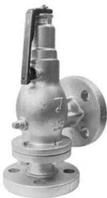
| Model | AL-400L | AL-400TL |
|---|---|---|
| Structure | Open type with lever | Closed type with lever*1 |
| Nominal size | 15~50A | 15~50A |
| Application fluid | Steam | Air, water, oil and other non-dangerous fluids |
| Working pressure | 0.05~1.6 MPa | 0.05~1.3 MPa |
| Temperature | 220°C | 5~120°C |
| Connection | JIS 10K FF Flanged2 / JIS 16K FF Flanged2 | JIS 10K FF Flanged2 / JIS 16K FF Flanged2 |
| Body / Spring case | Ductile cast iron (FCD450) | Ductile cast iron (FCD450) |
| Valve / Valve seat | Stainless steel | Stainless steel (With PTFE valve disc) |
*1 Closed type is a structure that does not allow any part of the blown fluid to be discharged to the outside except at the outlet. *2 JIS 16K FF flanges are used when the applicable pressure exceeds 1.0 MPa.
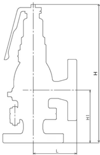
| Nominal size | L (mm) | H1 (mm) | H (mm) | Weight (kg) |
|---|---|---|---|---|
| 15A | 90 | 108 | 282 | 5.4 |
| 20A | 90 | 108 | 282 | 5.7 |
| 25A | 90 | 108 | 282 | 6.9 |
| 32A | 91 | 115 | 325 | 9.6 |
| 40A | 91 | 115 | 325 | 9.8 |
| 50A | 105 | 132 | 351 | 13.6 |
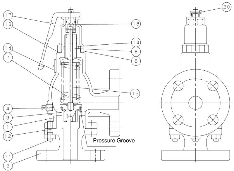
| No. | Name of Parts | Material |
|---|---|---|
| 1 | Spring Case | Ductile Cast Iron (FCD450) |
| 2 | Body | Ductile Cast Iron (FCD450) |
| 3 | Valve Seat | Stainless Steel (SUS304) |
| 4 | Valve / Valve · P | Cast Stainless Steel (SCS13 or SCS14A) |
| 7 | Spring | Piano Wire or Steel Wire (SWP or SWC) |
| 8 | Cap | Bronze (CAC406) |
| 9 | Adjusting Screw | Brass (C3604) |
| 10 | Lock Nut | Brass (C3604) |
| 11 | Stud Bolt & Nut | Steel |
| 12 | Gasket | Non-Asbestos |
| 13 | Gasket | Non-Asbestos |
| 14 | Name Plate | Aluminium (A1100P) |
| 15 | Spindle | Stainless Steel (SUS304) |
| 17 | Lever | Stainless Steel (SUS430) |
| 18 | Connecting Rod | Brass (C3604) |
| 20 | Pin | Stainless Steel (SUS) |
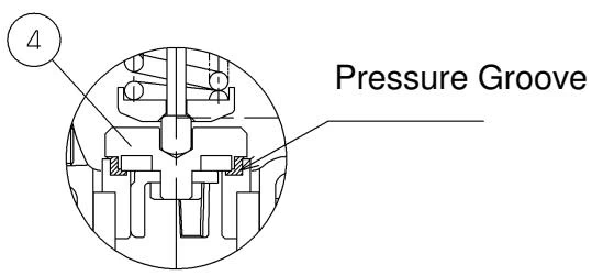 Figure: Valve Seat of AL-400TL (Same as AL-400L except for the valve seat).
Saturation temperature, Pressure vessel structure standard (kg/h)
| Nominal size \ Pressure MPa | 0.1 | 0.2 | 0.3 | 0.5 | 0.7 | 1.0 | 1.3 | 1.6 |
|---|---|---|---|---|---|---|---|---|
| 15A, 20A, 25A | 50 | 73 | 98 | 148 | 196 | 268 | 340 | 411 |
| 32A | 110 | 160 | 214 | 324 | 430 | 588 | 745 | 902 |
| 40A | 116 | 168 | 226 | 342 | 454 | 620 | 786 | 951 |
| 50A | 201 | 292 | 392 | 592 | 785 | 1073 | 1360 | 1646 |
20℃, Pressure vessel structure standard (kg/h)
| Nominal size \ Pressure MPa | 0.1 | 0.2 | 0.3 | 0.5 | 0.7 | 1.0 | 1.3 |
|---|---|---|---|---|---|---|---|
| 15A, 20A, 25A | 109 | 159 | 213 | 322 | 432 | 595 | 759 |
| 32A, 40A | 178 | 259 | 347 | 525 | 703 | 969 | 1236 |
| 50A | 325 | 473 | 635 | 959 | 1283 | 1769 | 2256 |
Accumulation: 25%, Yoshitake standard (m³/h)
| Nominal size \ Pressure MPa | 0.1 | 0.2 | 0.3 | 0.5 | 0.7 | 1.0 | 1.3 |
|---|---|---|---|---|---|---|---|
| 15A, 20A, 25A | 1.1 | 1.6 | 2.0 | 2.6 | 3.1 | 3.7 | 4.2 |
| 32A, 40A | 1.9 | 2.7 | 3.3 | 4.2 | 5.5 | 6.0 | 6.9 |
| 50A | 3.5 | 4.9 | 6.0 | 7.8 | 9.2 | 11.0 | 12.6 |
(Note: Capacity tables above show selected pressure points. Refer to full documentation for intermediate values).
WARNING
CAUTION
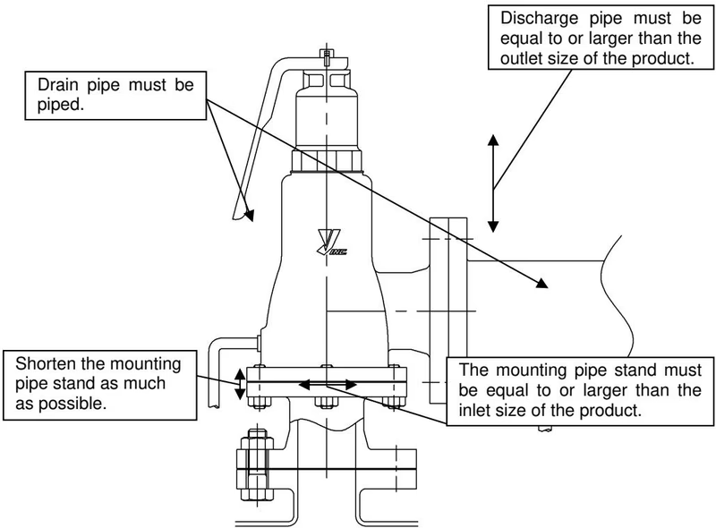
For steam applications, install the discharge pipe and expansion joints to ensure that the stress caused by the thermal expansion of the equipment and the thermal effects of the safety relief valve discharge does not affect the safety relief valve. The piping diameter of the discharge pipe should be at least equal to the outlet diameter of the product, and the piping should be designed to prevent back pressure.
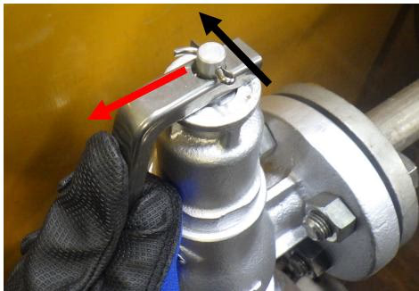
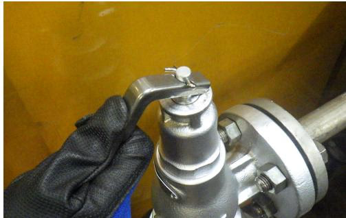
Lever Lifting Procedure: Position the lever perpendicular to the pin. If the lever is in a horizontal position, it may not lift or could be damaged when lifted. Lift the lever to initiate the discharge operation. Do not stand in front of the discharge pipe.
| Fault Condition | Cause | Countermeasures/Actions |
|---|---|---|
| Leakage from the outlet side | Debris or scale is lodged between the valve and valve seat. | Operate the safety relief valve to remove debris. If leakage persists, contact us. |
| Contact surface of the valve seat is damaged. | The product needs to be replaced. | |
| Misoperation due to vibration in the piping. | Cannot be used in systems with excessive vibration. | |
| External leakage | Gaskets are deteriorated or damaged. | Gaskets need to be replaced. |
| Operates at pressure lower than set pressure | Product specification does not match operating conditions. | Check set pressure on nameplate. Replace if conditions differ. |
| Pressure gauge is faulty. | Calibrate or replace the pressure gauge. | |
| Does not operate even at set pressure | Sliding parts between valve and valve seat are not moving smoothly. | Product needs to be returned, disassembled, and cleaned. |
| Back pressure in the outlet piping. | Remove back pressure. Modify piping layout. | |
| Valve remains in a continuously discharged state | Normal pressure is higher than the reseating pressure. | Increase the difference between set pressure and normal pressure. |
| Lever cannot be lifted | Inlet side pressure is low. | Increase inlet pressure to at least 75% of the set pressure. |
| Lever is not perpendicular to pin. | Adjust the lever to a perpendicular position relative to the pin and lift it. |
Yoshitake Safety Valves / Relief Valves
AF and AL series safety and relief valves for overpressure protection of steam, water, and air equipment.
Explore similar products in our catalog