Lift Type

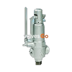
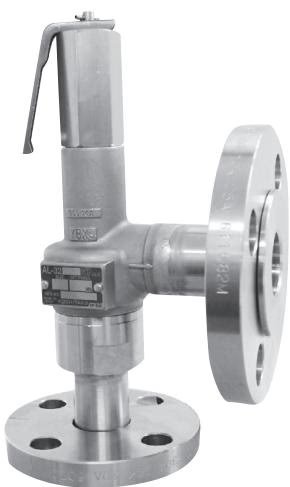
Yoshitake AL-32ML closed type safety relief valve with lever. All stainless steel construction offering high corrosion resistance. Suitable for air, water, and oil. Working pressure 0.05-1.0 MPa.
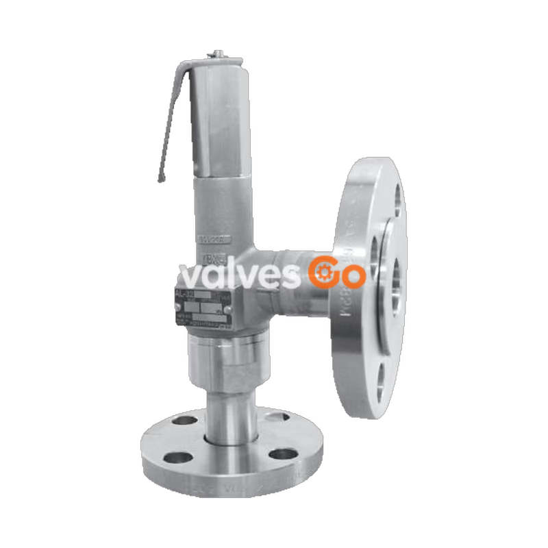
Yoshitake AL-32ML is a closed type safety relief valve with a lever. It is used mainly in various pressure vessels, instrumentation devices, and at the outlet of pressure reducing valves to prevent accidents caused by abnormal pressure rise. All stainless steel construction (SCS14A and SUS316 for trim parts) offers high corrosion resistance. The closed structure prevents fluid leakage, and a discharge inspection can be manually performed using the lever.
| Structure | Closed type with lever |
|---|---|
| Application | Air, water, oil, other non-dangerous fluid * |
| Working pressure | 0.05-1.0 MPa |
| Working temperature | 5-120°C |
| Connection | JIS 10K loose flange |
* Please contact us when using for oil.
WARNING
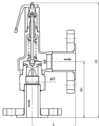
| Nominal size | Dimension D (mm) | Dimension L (mm) | Dimension H1 (mm) | Dimension H (mm) | Flow area (mm²) | Weight (kg) |
|---|---|---|---|---|---|---|
| 15A | 16 | 63 | 97 | 215 | 20.1 | 2.5 |
| 20A | 21 | 87 | 101 | 217 | 34.6 | 2.9 |
| 25A | 26 | 92 | 119 | 245 | 53.0 | 4.5 |
| 32A | 33 | 99 | 135 | 284 | 93.3 | 5.3 |
| 40A | 41 | 109 | 140 | 321 | 135.2 | 6.7 |
| 50A | 51 | 114 | 162 | 372 | 208.2 | 11.5 |
The outlet flange is 1 size larger than the nominal size.
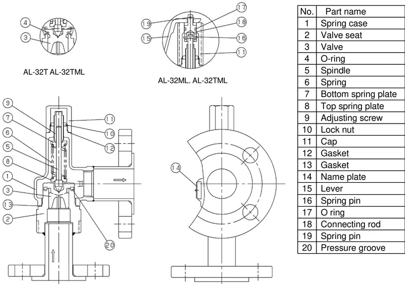
| No. | Part name |
|---|---|
| 1 | Spring case |
| 2 | Valve seat |
| 3 | Valve |
| 4 | O-ring |
| 5 | Spindle |
| 6 | Spring |
| 7 | Bottom spring plate |
| 8 | Top spring plate |
| 9 | Adjusting screw |
| 10 | Lock nut |
| 11 | Cap |
| 12 | Gasket |
| 13 | Gasket |
| 14 | Name plate |
| 15 | Lever |
| 16 | Spring pin |
| 17 | O ring |
| 18 | Connecting rod |
| 19 | Spring pin |
| 20 | Pressure groove |
Capacity <Pressure vessel structure standard> [kg/h]
| Nominal size \ Pressure (MPa) | 0.05 | 0.1 | 0.2 | 0.3 | 0.4 | 0.5 | 0.6 | 0.7 | 0.8 | 0.9 | 1.0 |
|---|---|---|---|---|---|---|---|---|---|---|---|
| 15A | 25 | 33 | 48 | 65 | 81 | 98 | 114 | 131 | 147 | 164 | 181 |
| 20A | 44 | 57 | 83 | 111 | 140 | 169 | 197 | 226 | 254 | 283 | 311 |
| 25A | 67 | 87 | 127 | 171 | 215 | 258 | 302 | 346 | 390 | 433 | 477 |
| 32A | 113 | 147 | 214 | 288 | 362 | 435 | 509 | 582 | 656 | 730 | 803 |
| 40A | 169 | 221 | 321 | 431 | 542 | 652 | 762 | 872 | 982 | 1093 | 1203 |
| 50A | 262 | 341 | 496 | 666 | 836 | 1006 | 1176 | 1346 | 1516 | 1687 | 1857 |
Capacity <Yoshitake standard> [m³/h]
| Nominal size \ Pressure (MPa) | 0.05 | 0.1 | 0.2 | 0.3 | 0.4 | 0.5 | 0.6 | 0.7 | 0.8 | 0.9 | 1.0 |
|---|---|---|---|---|---|---|---|---|---|---|---|
| 15A | 0.4 | 0.5 | 0.9 | 1.1 | 1.3 | 1.5 | 1.6 | 1.8 | 1.9 | 2.0 | 2.1 |
| 20A | 0.6 | 0.9 | 1.6 | 2.0 | 2.3 | 2.6 | 2.8 | 3.1 | 3.3 | 3.5 | 3.7 |
| 25A | 1.0 | 1.5 | 2.5 | 3.1 | 3.6 | 4.0 | 4.4 | 4.7 | 5.1 | 5.4 | 5.7 |
| 32A | 1.8 | 2.6 | 4.5 | 5.5 | 6.3 | 7.1 | 7.8 | 8.4 | 9.0 | 9.5 | 10.0 |
| 40A | 2.7 | 3.8 | 6.5 | 7.9 | 9.2 | 10.3 | 11.3 | 12.2 | 13.0 | 13.8 | 14.6 |
| 50A | 4.1 | 5.9 | 10.0 | 12.3 | 14.2 | 15.9 | 17.4 | 18.8 | 20.1 | 21.3 | 22.4 |
As the inlet pressure approaches the blowout pressure, the force of fluid pushing up the valve approaches the force of the spring pressing down the valve. The safety relief valve commences to blow when the inlet pressure reaches around 3% below the blowout pressure. The fluid accumulates gradually on the pressure groove and when the fluid pressure reaches the blowout pressure the valve pops.
Since the inlet pressure of the safety relief valve decreases when the fluid is released into the atmosphere by the pop action of the valve, the force of fluid lift is lowered. At this point, the repelling force of the spring becomes larger than the force of fluid lift and thus the valve closes. In addition, while the safety relief valve discharges, pressure of fluid entering into the back of the valve (back pressure) adds to the closing force.
WARNING
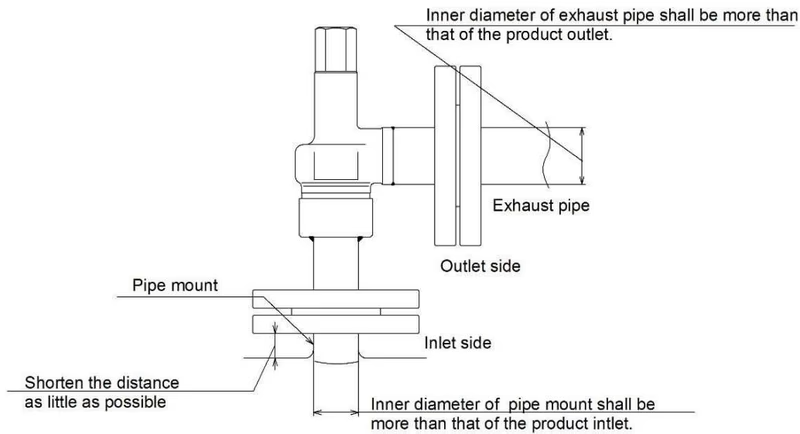
Check the following items while the system is in operation:
Check that there is no loose piping at the inlet and outlet side of the product and that the cap is fastened securely. For the AL-32ML, check the operation by lifting up the lever, while differential pressure between the set and inlet pressures is within the allowed range.
Required differential pressure at a discharge inspection
| Nominal size | Difference between set pressure at a discharge inspection |
|---|---|
| 15A-25A | 1.0 MPa or less |
| 32A, 40A | 0.6 MPa or less |
| 50A | 0.4 MPa or less |
Yoshitake Safety Valves / Relief Valves
AF and AL series safety and relief valves for overpressure protection of steam, water, and air equipment.
Explore similar products in our catalog