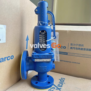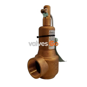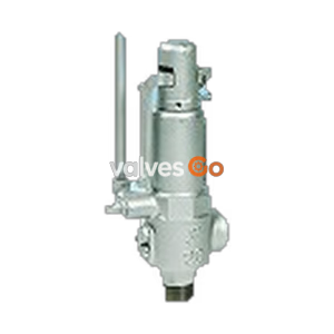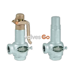
Lift Type

Yoshitake AL-150 closed-type safety relief valve for steam, air, water, and oil. Features stainless steel trim, 0.05-1.0 MPa working pressure, and 15-50A sizes.
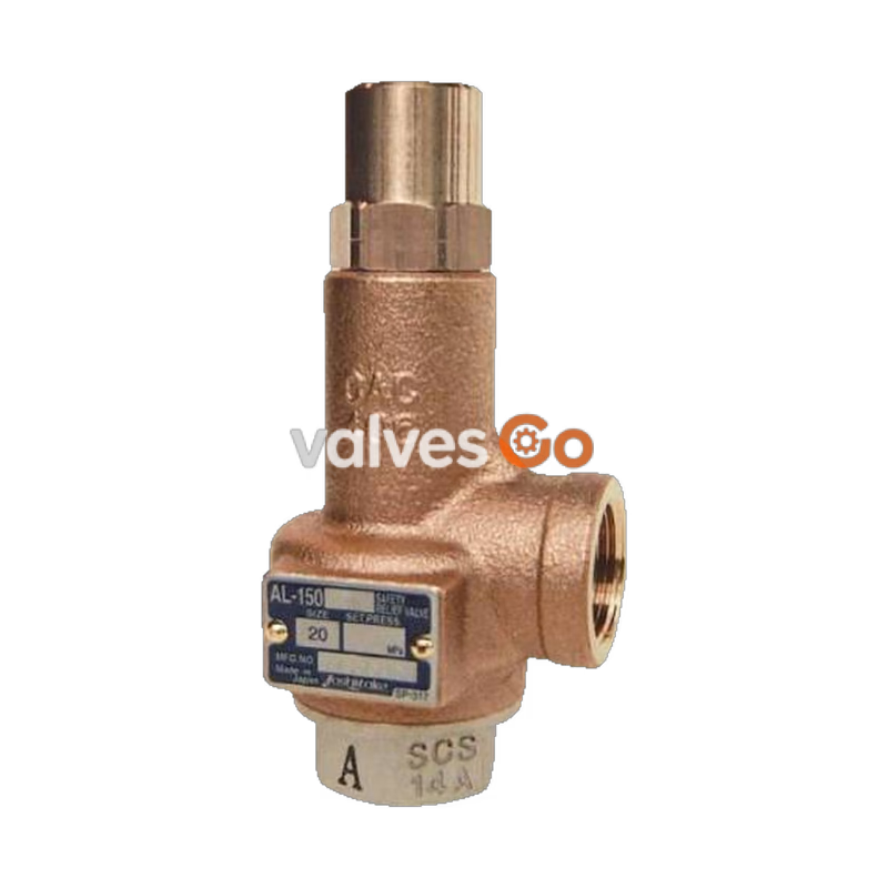
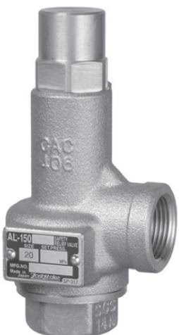
Yoshitake AL-150 is a versatile, closed-type safety relief valve compatible with fluids such as steam, air, water, and oil. It is mainly used in various pressure vessels, instrumentation devices, and at the outlet of pressure reducing valves to prevent accidents caused by abnormal pressure rise. The trim parts (valve and valve seat) and adjusting spring are made of high-quality stainless steel, ensuring outstanding corrosion resistance and reliable performance.
| Specification | Value |
|---|---|
| Structure | Closed type |
| Application | Steam, Air, Hot and cold water, Oil, Other non-dangerous fluids |
| Working pressure | 0.05 - 1.0 MPa |
| Working temperature | 5 - 220°C (Max 150°C when using for water, oil, or other liquids) |
| Connection | JIS Rc screwed |
| Material (Spring case) | Bronze / Cast bronze |
| Material (Valve, Valve seat) | Stainless steel (SCS14A) |
| Material (Adjusting spring) | Stainless steel |
Note
AL-150T is recommended for hot and cold water applications.
WARNING
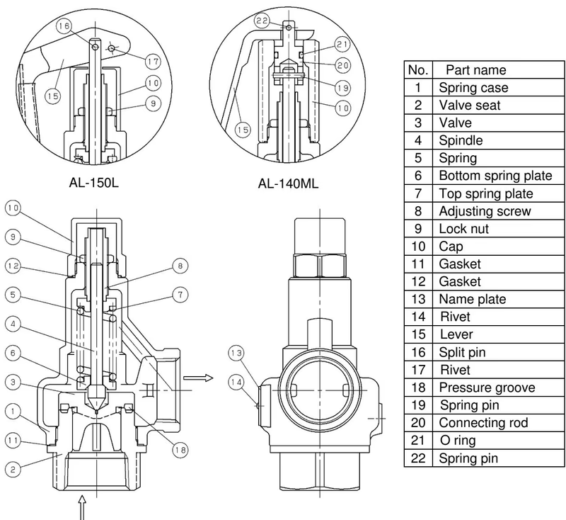
| No. | Part Name | Material |
|---|---|---|
| 1 | Spring case | Bronze (CAC406) |
| 2 | Valve seat | Cast Stainless Steel (SCS14A) |
| 3 | Valve | Cast Stainless Steel (SCS14A) |
| 4 | Spindle | Brass |
| 5 | Spring | Stainless Steel (SUS304) |
| 6 | Bottom spring plate | Brass |
| 7 | Top spring plate | Brass |
| 8 | Adjusting screw | Brass |
| 9 | Lock nut | Brass |
| 10 | Cap | Brass |
| 11 | Gasket | PTFE |
| 12 | Gasket | PTFE |
| 13 | Name plate | Stainless Steel (SUS304) |
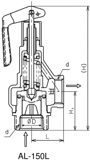
| Nominal size | d | D (mm) | L (mm) | H1 (mm) | H (mm) | Flow area (mm²) | Weight (kg) |
|---|---|---|---|---|---|---|---|
| 15A | Rc 1/2 | 16 | 34 | 40 | 128 | 20.1 | 0.7 |
| 20A | Rc 3/4 | 21 | 38 | 43 | 128.5 | 34.6 | 0.8 |
| 25A | Rc 1 | 26 | 43 | 51.5 | 144.5 | 53.0 | 1.1 |
| 32A | Rc 1-1/4 | 33 | 50 | 61.5 | 181.5 | 93.3 | 1.8 |
| 40A | Rc 1-1/2 | 41 | 60 | 60 | 205 | 135.2 | 2.8 |
| 50A | Rc 2 | 51 | 75 | 76 | 245.5 | 208.2 | 4.7 |
As the inlet pressure approaches the blowout pressure, the force of fluid pushing up the valve approaches the force of the spring pressing down the valve. The safety relief valve commences to blow when the inlet pressure reaches around 3% below the blowout pressure. The fluid accumulates gradually on the pressure groove and when the fluid pressure reaches the blowout pressure the valve pops.
Since the inlet pressure of the safety relief valve decreases when the fluid is released into the atmosphere by the pop action of the valve, the force of fluid lift is lowered. At this point, the repelling force of the spring becomes larger than the force of fluid lift and thus the valve closes. In addition, while the safety relief valve discharges, pressure of fluid entering into the back of the valve (back pressure) adds to the closing force.
Capacity according to Pressure vessel structure standard (kg/h):
| Nominal size \ Pressure MPa | 0.05 | 0.1 | 0.2 | 0.3 | 0.4 | 0.5 | 0.6 | 0.7 | 0.8 | 0.9 | 1.0 | | --- | --- | --- | --- | --- | --- | --- | --- | --- | --- | --- | | 15A | 15 | 20 | 29 | 40 | 50 | 60 | 70 | 80 | 90 | 100 | 109 | | 20A | 27 | 35 | 51 | 69 | 87 | 104 | 121 | 138 | 155 | 172 | 189 | | 25A | 42 | 54 | 78 | 105 | 133 | 159 | 186 | 212 | 237 | 263 | 289 | | 32A | 70 | 91 | 132 | 178 | 224 | 268 | 313 | 356 | 400 | 443 | 487 | | 40A | 105 | 136 | 198 | 266 | 335 | 402 | 468 | 534 | 599 | 664 | 729 | | 50A | 163 | 211 | 306 | 411 | 518 | 621 | 723 | 824 | 924 | 1025 | 1126 |
Capacity according to Pressure vessel structure standard (kg/h):
| Nominal size \ Pressure MPa | 0.05 | 0.1 | 0.2 | 0.3 | 0.4 | 0.5 | 0.6 | 0.7 | 0.8 | 0.9 | 1.0 | | --- | --- | --- | --- | --- | --- | --- | --- | --- | --- | --- | | 15A | 25 | 33 | 48 | 65 | 81 | 98 | 114 | 131 | 147 | 164 | 181 | | 20A | 44 | 57 | 83 | 111 | 140 | 169 | 197 | 226 | 254 | 283 | 311 | | 25A | 67 | 87 | 127 | 171 | 215 | 258 | 302 | 346 | 390 | 433 | 477 | | 32A | 113 | 147 | 214 | 288 | 362 | 435 | 509 | 582 | 656 | 730 | 803 | | 40A | 169 | 221 | 321 | 431 | 542 | 652 | 762 | 872 | 982 | 1093 | 1203 | | 50A | 262 | 341 | 496 | 666 | 836 | 1006 | 1176 | 1346 | 1516 | 1687 | 1857 |
Capacity according to Yoshitake standard (m³/h):
| Nominal size \ Pressure MPa | 0.05 | 0.1 | 0.2 | 0.3 | 0.4 | 0.5 | 0.6 | 0.7 | 0.8 | 0.9 | 1.0 | | --- | --- | --- | --- | --- | --- | --- | --- | --- | --- | --- | | 15A | 0.4 | 0.5 | 0.9 | 1.1 | 1.3 | 1.5 | 1.6 | 1.8 | 1.9 | 2.0 | 2.1 | | 20A | 0.6 | 0.9 | 1.6 | 2.0 | 2.3 | 2.6 | 2.8 | 3.1 | 3.3 | 3.5 | 3.7 | | 25A | 1.0 | 1.5 | 2.5 | 3.1 | 3.6 | 4.0 | 4.4 | 4.7 | 5.1 | 5.4 | 5.7 | | 32A | 1.8 | 2.6 | 4.5 | 5.5 | 6.3 | 7.1 | 7.8 | 8.4 | 9.0 | 9.5 | 10.0 | | 40A | 2.7 | 3.8 | 6.5 | 7.9 | 9.2 | 10.3 | 11.3 | 12.2 | 13.0 | 13.8 | 14.6 | | 50A | 4.1 | 5.9 | 10.0 | 12.3 | 14.2 | 15.9 | 17.4 | 18.8 | 20.1 | 21.3 | 22.4 |
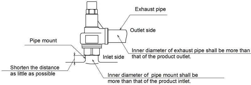
Warning
Installation Cautions
Check the following items while the system is in operation:
| Trouble | Cause | Remedy |
|---|---|---|
| Leakage detected visually/aurally at the outlet | 1. Foreign substance or scale stuck on contact surface between the valve and valve seat. 2. Damage on contact surfaces. 3. Excessive vibration applied to the piping. 4. Pressure difference between set pressure and normal working pressure is too small. | 1. Operate the product to eliminate the foreign substance. 2. Disassemble and replace parts. 3. Do not use on excessively vibrating equipment. 4. Increase the pressure difference. |
| Blows at a pressure lower than the set pressure | 1. Product specifications are not consistent with the use condition. 2. Pressure gauge is out of order. 3. Product does not keep the accuracy of its set pressure. | 1. Check set pressure indication. Replace if unsuitable. 2. Calibrate or replace pressure gauge. 3. Readjust set pressure. |
| Does not operate at the set pressure | 1. Product specifications are not consistent with the use condition. 2. Pressure gauge is out of order. 3. Sliding parts do not move smoothly. 4. Back pressure at the outlet piping. | 1. Replace with a proper model. 2. Calibrate or replace pressure gauge. 3. Disassemble and clean. 4. Remove back pressure. |
| Does not stop blowing | 1. Foreign substance or scale stuck on contact surface. 2. Sliding parts do not move smoothly. 3. Normal working pressure exceeds closing pressure. | 1. Start up the product to remove scale. 2. Disassemble and clean. 3. Increase difference between set pressure and normal working pressure. |
Yoshitake Safety Valves / Relief Valves
AF and AL series safety and relief valves for overpressure protection of steam, water, and air equipment.
Explore similar products in our catalog