Lift Type

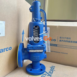
Yoshitake AF-10EN full bore safety valve for steam, air, and non-dangerous gases. Features ductile cast iron body, EN PN16 flanged connection, and 0.1-1.6 MPa working pressure.
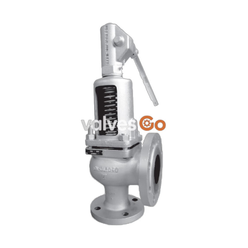
The Yoshitake AF-10EN is a full bore safety valve with an open-type lever structure, designed in accordance with ISO4126-1: 2013. It is engineered for use with steam, air, and other non-dangerous gases, providing a large discharge capacity and highly reliable operation. The valve features a ductile cast iron body and stainless steel valve and seat, ensuring durability under demanding conditions. A key operational advantage is the ability to manually perform discharge inspections using the lever when the inlet pressure reaches 80% or more of the set pressure.
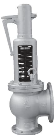
| Parameter | Description |
|---|---|
| Model | AF-10EN |
| Structure | Open type with lever |
| Application | Steam, Air, and Other non-dangerous gases *1 |
| Nominal size | 20A x 32A, 25A x 40A, 32A x 50A, 40A x 65A, 50A x 80A, 65A x 100A, 80A x 125A, 100A x 150A |
| Working pressure | 0.1 to 1.6 MPa *2 |
| Maximum temperature | 250 °C *2 |
| Material (Body / Spring chamber) | Ductile cast iron |
| Material (Valve / Valve seat) | Stainless steel |
| Connection | EN PN16 flanged (Outlet is two sizes larger than inlet) |
*1 The valve cannot be used for liquid application. *2 The relationship between working pressure and temperature as per EN1092-2.
| A | B | C | D | E |
|---|---|---|---|---|
| 0.1 – 0.15 MPa | 0.15 – 0.2 MPa | 0.2 – 0.25 MPa | 0.25 – 0.35 MPa | 0.35 – 0.45 MPa |
| F | G | H | I |
|---|---|---|---|
| 0.45 – 0.65 MPa | 0.65 – 0.85 MPa | 0.85 – 1.2 MPa | 1.2 – 1.6 MPa |
According to EN1092-2 (PN16):
| Material | up to 120 °C | 150 °C | 200 °C | 250 °C |
|---|---|---|---|---|
| Ductile cast iron | 1.6 MPa | 1.55 MPa | 1.47 MPa | 1.39 MPa |
Note: Intermediate values may be obtained by linear interpolation.
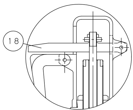
Parts List:
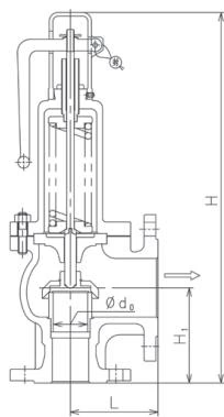
| Nominal size | Inlet x Outlet | Throat dia. d0 (mm) | Flow area (mm²) | L (mm) | H1 (mm) | H (mm) | Weight (kg) |
|---|---|---|---|---|---|---|---|
| 20A | 20 x 32 | 18.5 | 268 | 85 | 85 | 360 | 10 |
| 25A | 25 x 40 | 23 | 415 | 100 | 100 | 375 | 11 |
| 32A | 32 x 50 | 29.5 | 683 | 105 | 110 | 450 | 15 |
| 40A | 40 x 65 | 36.5 | 1046 | 115 | 125 | 470 | 17 |
| 50A | 50 x 80 | 46 | 1661 | 120 | 130 | 510 | 24 |
| 65A | 65 x 100 | 59.5 | 2780 | 140 | 160 | 680 | 38 |
| 80A | 80 x 125 | 73 | 4185 | 160 | 180 | 785 | 53 |
| 100A | 100 x 150 | 91 | 6503 | 180 | 200 | 895 | 78 |
For Steam (saturation temperature) <EN ISO 4126-1: 2013> (kg/h)
| Nominal size | 0.1 MPa | 0.3 MPa | 0.5 MPa | 0.7 MPa | 0.9 MPa | 1.1 MPa | 1.3 MPa | 1.6 MPa |
|---|---|---|---|---|---|---|---|---|
| 20A | 224 | 451 | 676 | 899 | 1120 | 1341 | 1560 | 1889 |
| 25A | 348 | 699 | 1047 | 1392 | 1735 | 2077 | 2416 | 2926 |
| 32A | 573 | 1151 | 1723 | 2291 | 2856 | 3418 | 3977 | 4816 |
| 40A | 877 | 1762 | 2639 | 3509 | 4374 | 5235 | 6090 | 7376 |
| 50A | 1393 | 2799 | 4191 | 5572 | 6946 | 8313 | 9671 | 11713 |
| 65A | 2332 | 4684 | 7015 | 9326 | 11625 | 13913 | 16187 | 19604 |
| 80A | 3511 | 7052 | 10561 | 14039 | 17501 | 20945 | 24368 | 29513 |
| 100A | 5457 | 10959 | 16411 | 21815 | 27195 | 32547 | 37866 | 45859 |
For Air (20 ℃) <EN ISO 4126-1: 2013> (kg/h)
| Nominal size | 0.1 MPa | 0.3 MPa | 0.5 MPa | 0.7 MPa | 0.9 MPa | 1.1 MPa | 1.3 MPa | 1.6 MPa |
|---|---|---|---|---|---|---|---|---|
| 20A | 353 | 724 | 1095 | 1466 | 1837 | 2208 | 2578 | 3135 |
| 25A | 548 | 1122 | 1696 | 2270 | 2844 | 3419 | 3993 | 4854 |
| 32A | 902 | 1847 | 2792 | 3737 | 4682 | 5627 | 6572 | 7989 |
| 40A | 1381 | 2828 | 4276 | 5723 | 7170 | 8617 | 10065 | 12235 |
| 50A | 2193 | 4491 | 6790 | 9088 | 11386 | 13684 | 15982 | 19430 |
| 65A | 3671 | 7518 | 11364 | 15211 | 19057 | 22903 | 26750 | 32520 |
| 80A | 5527 | 11317 | 17108 | 22898 | 28689 | 34479 | 40269 | 48955 |
| 100A | 8588 | 17586 | 26584 | 35581 | 44579 | 53577 | 62574 | 76071 |
(Note: Intermediate pressure values are available in the full manual tables.)
WARNING
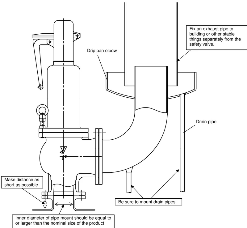
INSTALLATION CAUTIONS
Daily Inspection:
Periodic Inspection (Monthly):
| Trouble | Cause | Remedy |
|---|---|---|
| Leakage from outlet | Foreign substance is stuck between valve and valve seat. | Operate the product to eliminate foreign substances. |
| Sealing surface of valve seat is damaged. | The product needs to be replaced. | |
| Vibration transmitted from the piping causes malfunction. | Do not use the product on equipment that vibrates excessively. | |
| Blows at a pressure lower than the set pressure | Product specifications are not consistent with usage conditions. | Check the set pressure value shown on the nameplate. |
| Pressure gauge is out of order. | Calibrate or replace the pressure gauge. | |
| Does not blow at the set pressure | Sliding parts of the valve and valve seat do not move smoothly. | The product needs to be disassembled and cleaned. |
| There is a back pressure at the piping of the product outlet. | Remove the back pressure by changing the piping layout. | |
| The lever does not lift up | Inlet pressure is too low. | Increase the inlet pressure to 80% of the set pressure or higher. |
Yoshitake Safety Valves / Relief Valves
AF and AL series safety and relief valves for overpressure protection of steam, water, and air equipment.
Explore similar products in our catalog