Up to 99.8% Efficiency

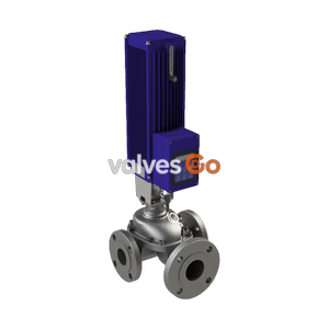
TLV PN-COS-16 pneumatic control valve for steam. Features a rapid response actuator, built-in cyclone separator, and free float steam trap for dry, high-quality steam.
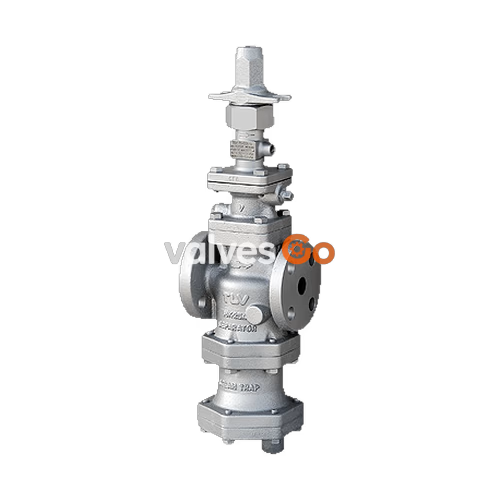
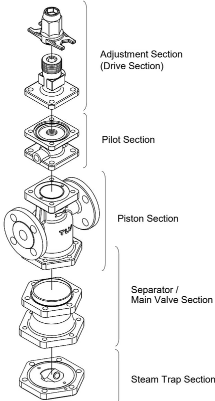
TLV PN-COS-16 is a remotely controllable pneumatically actuated control valve for steam. It utilizes the structure of the COSPECT series pilot operated pressure reducing valve. Steam-using equipment can achieve its intended efficiency only if the steam being used is very dry. The PN-COS-16 features a built-in cyclone separator, screen, and steam trap that eliminates entrained condensate and scale, making possible the supply of very dry steam at a stable pressure.
The PN-COS-16 can operate automatically and provide accurate pressure control and temperature control when combined with a digital indicator controller or a general-purpose controller. Additionally, manual remote setting or 2-point pressure switching is possible by combination with an air regulator.
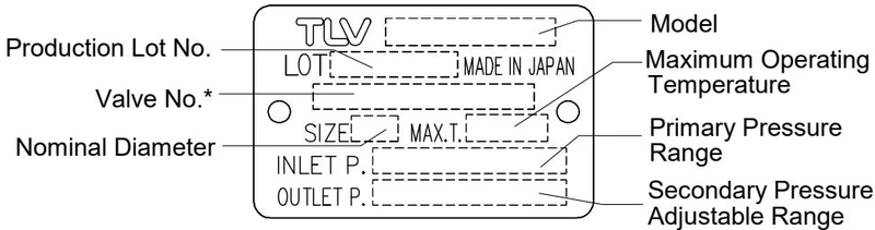
| Specification | Value |
|---|---|
| Body Material | Cast Iron (FC250/GG-25), Ductile Cast Iron (GGG40.3), Cast Stainless Steel (A351 Gr.CF8/CF8M) |
| Connection | Flanged (ASME, DIN) |
| Size | DN 15, 20, 25, 40, 50 |
| Max. Operating Pressure (PMO) | 16 barg (1.6 MPaG) |
| Max. Operating Temperature (TMO) | 220 °C |
| Primary Pressure Range | 2 - 16 barg (0.2 - 1.6 MPaG) |
| Adjustable Pressure Range | Within 10 - 84% of primary pressure (Minimum 0.3 barg) |
| Minimum Adjustable Flow Rate | 5% of rated flow rate |
| Motive Medium | Oil-free air, filtered to 5 μm |
| Required Motive Air Pressure | [Desired secondary pressure + 1] barg or higher |
WARNING
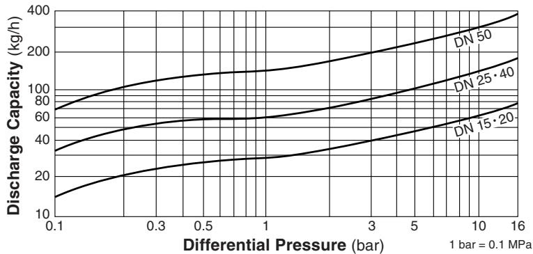
DO NOT use the product in excess of the maximum operating pressure differential; such use could make discharge through the steam trap impossible (blocked).
| Nominal Valve Size (DN) | 15 | 20 | 25 | 40 | 50 |
|---|---|---|---|---|---|
| Kvs (DIN) | 3.3 | 5.9 | 9.5 | 20.6 | 31.9 |
| Cv (UK) | 3.2 | 5.7 | 9.2 | 20.0 | 31.0 |
| Cv (US) | 3.8 | 6.9 | 11.1 | 24.0 | 37.2 |
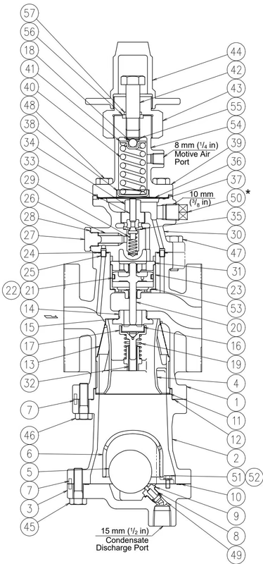
| No. | Description | Material |
|---|---|---|
| 1 | Main Body | Cast Iron / Ductile Cast Iron / Cast Stainless Steel |
| 2 | Trap Body | Same material as Main Body |
| 3 | Trap Cover | Same material as Main Body |
| 4 | Separator | Cast Stainless Steel |
| 5 | Float | Stainless Steel |
| 6 | Float Cover | Cast Iron / Cast Stainless Steel |
| 7 | Trap Valve Seat | Stainless Steel |
| 8 | Separator Screen | Stainless Steel |
| 9 | Main Valve Seat | Stainless Steel |
| 10 | Main Valve | Stainless Steel |
| 12 | Piston | Cast Stainless Steel |
| 13 | Cylinder | Stainless Steel |
| 14 | Pilot Screen | Stainless Steel |
| 16 | Pilot Body | Same material as Main Body |
| 18 | Pilot Valve | Stainless Steel |
| 20 | Diaphragm | Stainless Steel |
| 23 | Coil Spring | Carbon Steel |
| 24 | Adjustment Screw | Carbon Steel |
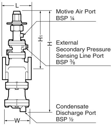
| DN | L (DIN PN25/40) | L (ASME 150RF) | L (ASME 300RF) | H | H1 | W | Weight (kg) |
|---|---|---|---|---|---|---|---|
| 15 | 150 | 170 | 170 | 537 | 327 | 105 | 17 |
| 20 | 150 | 182 | 182 | 537 | 327 | 105 | 18 |
| 25 | 160 | 188 | 192 | 564 | 324 | 150 | 23 |
| 40 | 200 | 220 | 224 | 614 | 344 | 165 | 29 |
| 50 | 230 | 255 | 261 | 677 | 357 | 195 | 44 |
(Weight is for PN 25/40)
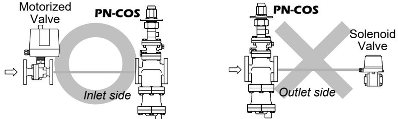
If an on-off valve, such as a motorized valve, is required to stop supply of steam to the steam-using equipment, install it at the inlet side of the PN-COS-16. If a solenoid valve is installed at the outlet, its opening and closing will cause heavy chattering and may lead to damage of the piston and main valve.
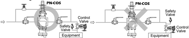
A control valve installed between the PN-COS-16 and the steam-using equipment for controlling equipment temperature may raise the pressure between the PN-COS-16 and the control valve when the control valve is closed. A safety valve should be installed downstream of the control valve.
To ensure long service life of the PN-COS-16, the following inspection and maintenance should be performed regularly.
| Part | Inspection and Maintenance Frequency |
|---|---|
| Screens (Separator, Pilot) | Disassemble and clean annually. |
| Main Valve, Pilot Valve | Replace after approximately 15,000 hours. |
| Piston Ring | Replace after approximately 8,000 hours. |
| Piston | Replace after approximately 30,000 hours. |
| Trap Valve Seat | Replace after approximately 40,000 hours. |
| Diaphragm | Replace after approximately 30,000 hours. |
DANGER
NEVER apply direct heat to the float. The float may explode due to increased internal pressure, causing accidents leading to serious injury or damage to property and equipment.
Explore similar products in our catalog