
ISO 9001 Certified
GESTRA RK 76 flanged wafer check valve is suitable for DN15-100, NPS½-4, supports PN6/10/16/25/40 and ASME Class125/150/300, prevents backflow in pipelines, suitable for liquids, gases, steam and other media, flexible installation, reliable sealing performance, meeting various application requirements.
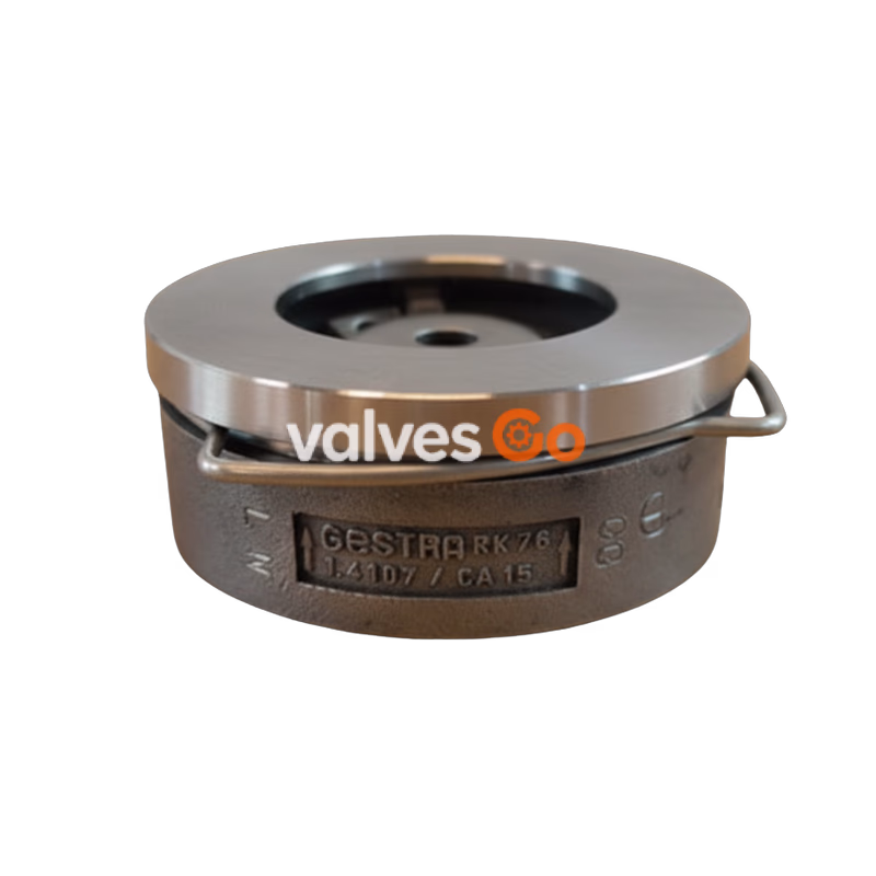
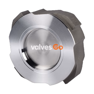
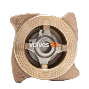
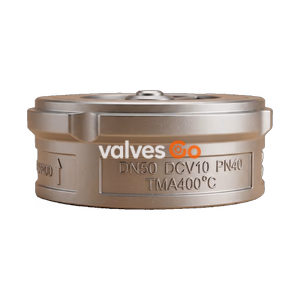
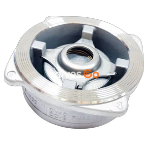
GESTRA RK 76 series flanged wafer check valves (also known as non-return valves) are specifically designed to prevent backflow in pipelines, featuring a wafer-type construction that can be directly clamped between two flanges for convenient installation. The product is equipped with a spiral centering ring to ensure precise installation alignment. It supports two designs: with spring (installable in any position) and without spring (suitable only for vertical pipelines with upward flow). The valve is suitable for various media including liquids, gases, steam and corrosive fluids, with pressure ratings covering PN6 to PN40 and ASME Class125 to 300, widely used in industrial pipeline systems.
| Temperature (℃) | -10 | 20 | 50 | 100 | 150 | 200 | 250 | 300 |
|---|---|---|---|---|---|---|---|---|
| Working pressure (barg) | 40.0 | 40.0 | 40.0 | 38.1 | 34.2 | 30.2 | 28.0 | 25.8 |
| Temperature (℃) | -10 | 20 | 50 | 100 | 150 | 200 | 250 | 300 |
|---|---|---|---|---|---|---|---|---|
| Working pressure (barg) | 49.6 | 49.6 | 48.1 | 42.2 | 38.5 | 35.7 | 33.4 | 31.6 |
| Disc Seal Material | Minimum Temperature (℃) | Maximum Temperature (℃) | Applicable Media | Leakage Class |
|---|---|---|---|---|
| Metal-to-metal | -10 | 300 | Liquids, gases, steam | DIN EN 12266 Class D |
| PTFE | -190 | 250 | Corrosive fluids | DIN EN 12266 Class D |
| EPDM | -40 | 150 | Water, condensate, steam | DIN EN 12266 Class A |
| FPM | -25 | 200 | Mineral oils, gases, air | DIN EN 12266 Class A |
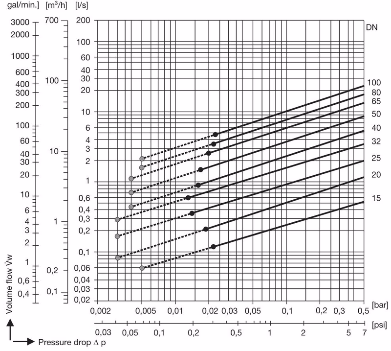
| Nominal Port Size (DN) | Without Spring (X) (mbar) | With Spring (X) (mbar) | With Spring (V) (mbar) | With Spring (Y) (mbar) |
|---|---|---|---|---|
| 15 | 2.5 | 10 | 7.5 | 5 |
| 20 | 2.5 | 10 | 7.5 | 5 |
| 25 | 2.5 | 10 | 7.5 | 5 |
| 32 | 3.5 | 12 | 8.5 | 5 |
| 40 | 4.0 | 13 | 9 | 5 |
| 50 | 4.5 | 14 | 9.5 | 5 |
| 65 | 5.0 | 15 | 10 | 5 |
| 80 | 5.5 | 16 | 10.5 | 5 |
| 100 | 6.5 | 18 | 11.5 | 5 |
Note: Special springs can be customized with cracking pressure ranges: DN15-50: 20-1000 mbar, DN65-80: 20-700 mbar, DN100: 20-500 mbar, additional charge applies.
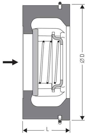
| Nominal Port Size (DN) | Nominal Port Size (inch) | Length (L) | Outer Diameter (∅D) (PN6-40) |
|---|---|---|---|
| 15 | ½ | 16 | 45 |
| 20 | ¾ | 19 | 55 |
| 25 | 1 | 22 | 65 |
| 32 | 1¼ | 28 | 75 |
| 40 | 1½ | 31.5 | 85 |
| 50 | 2 | 40 | 98 |
| 65 | 2½ | 46 | 118 |
| 80 | 3 | 50 | 134 |
| 100 | 4 | 60 | 154 |
Note: Length (L) complies with EN 558 basic series 49 (equivalent to DIN 3202-3 series K4).
| Nominal Port Size (DN) | 15 | 20 | 25 | 32 | 40 | 50 | 65 | 80 | 100 |
|---|---|---|---|---|---|---|---|---|---|
| Weight (kg) | 0.18 | 0.30 | 0.45 | 0.70 | 0.90 | 1.50 | 2.10 | 3.40 | 5.20 |
| Component Name | DIN/EN Standard Material | ASME Standard Material | Material Category |
|---|---|---|---|
| Body, Seat, Guide ribs | 1.4107 | SA217 CA15 | Chromium steel |
| Disc, Spring seat | 1.4571 | - | Stainless steel |
| Spring | - | Stainless steel | Stainless steel |
| Spiral centering ring | 1.4310 | - | Chromium steel |
For information on chemical compatibility between valve materials and specific media, visit www.gestra.com, navigate to "Technical Support" and "Chemical resistance" for detailed information.
When ordering, the following parameters must be specified:
EN 10204 standard inspection certificates can be provided as verification evidence for material and construction testing. All testing requirements must be clearly stated in the quotation request or order. Inspection certificates will not be issued after delivery. Standard testing scope and costs are detailed in the price list "Standard Equipment Testing and Inspection Costs". For customized testing scope, please request a separate quotation.