
Analog Signal Control
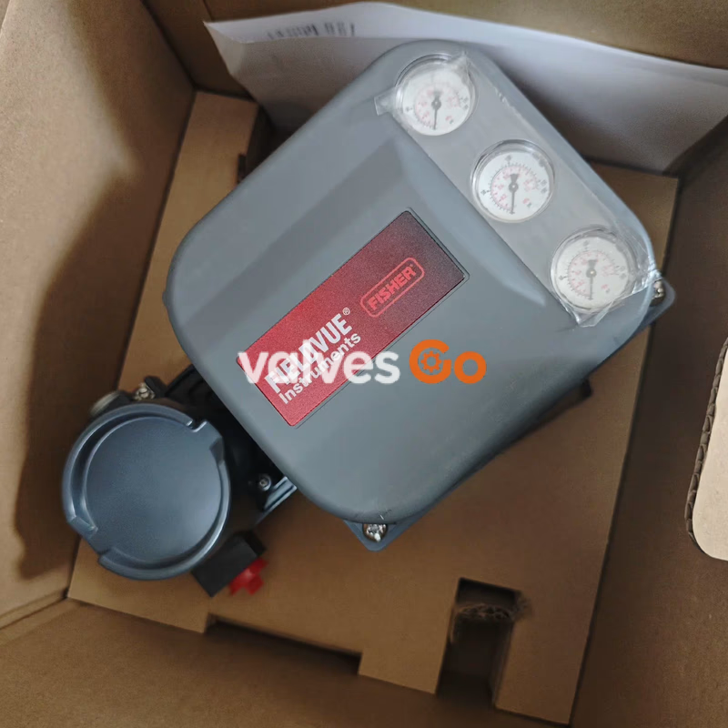
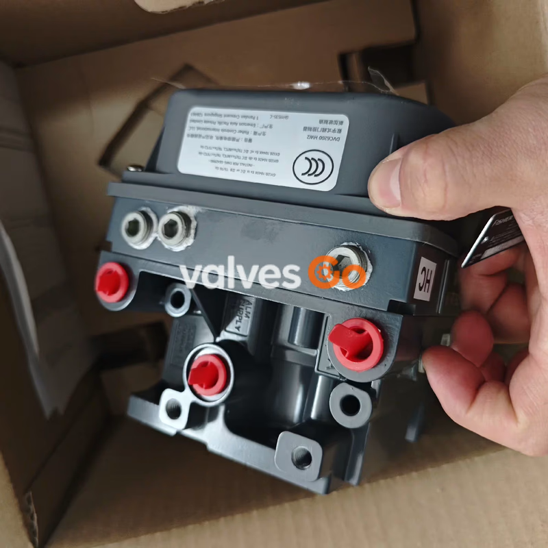
Fisher DVC6200 digital valve controller uses HART communication protocol, supports 4-20mA signal input, features automatic calibration and advanced diagnostics, compatible with multiple actuators, operating temperature -40 to 85°C, IP66 protection rating, providing precise and reliable valve position control solutions for industrial process control.
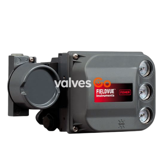
Emerson Fisher DVC6200 digital valve controller is a communication-based microprocessor instrument that combines traditional positioner functions with digital technology, replacing standard pneumatic and electro-pneumatic valve positioners. Its core advantage lies in providing convenient access to critical process operation information through HART communication protocol, including process component and control valve status data, supporting connections via handheld communicators, computers, or operator consoles. The product features automatic calibration, custom characterization curves, and advanced diagnostics, suitable for process control requirements in petroleum, chemical, power, and other industrial sectors. It is certified by CSA, FM, ATEX, IECEx, and other international standards, ensuring reliable operation in hazardous areas and harsh conditions.
| Parameter Category | Detailed Specifications |
|---|---|
| Input Signal Characteristics | Point-to-point mode: 4-20mA DC (nominal), split-rangeable; Minimum control current 4.0mA, minimum current without microprocessor restart 3.5mA; Minimum available voltage at instrument terminals 9.5VDC (analog control)/10VDC (HART communication) |
| Supply Requirements | Medium: Clean, dry, non-corrosive air or natural gas; Complies with ISA 7.0.01 and ISO 8573-1 standards (particle size class 7, oil content class 3, dew point class 3 or 10°C below minimum ambient temperature) |
| Air Consumption | Standard relay: <0.38 normal m³/hr (14scfh) at 1.4bar (20psig), <1.3 normal m³/hr (49scfh) at 5.5bar (80psig); Low bleed relay: Average 0.056 normal m³/hr (2.1scfh) at 1.4bar, average 0.184 normal m³/hr (6.9scfh) at 5.5bar |
| Maximum Output Capacity | 10.0 normal m³/hr (375scfh) at 1.4bar (20psig); 29.5 normal m³/hr (1100scfh) at 5.5bar (80psig) |
| Electrical Protection | Reverse polarity protection, overcurrent protection; Hazardous area certifications include intrinsically safe, explosion-proof, dust ignition-proof, etc. |
| Product Model | Construction Material | Weight (kg) | Weight (lbs) |
|---|---|---|---|
| DVC6200 | Aluminum construction | 3.5 | 7.7 |
| DVC6200 | Stainless steel body | 8.6 | 19 |
| DVC6205 | Standard configuration | 4.1 | 9 |
| DVC6215 | Feedback unit | 1.4 | 3.1 |
| Component | Material Specification | Notes |
|---|---|---|
| Housing, module base, terminal box | Standard: A03600 low-copper aluminum alloy; Optional: Stainless steel | Meets explosion-proof and corrosion resistance requirements |
| Cover | Thermoplastic polyester | - |
| Elastomers | Standard: Nitrile; Extreme temperature option: Fluorosilicone | Suitable for different temperature conditions |
| Main components | Stainless steel | Ensures structural strength and corrosion resistance |
| Seals | O-rings (Nitrile/Fluorosilicone) | Select material according to operating conditions |
| Printed Wiring Board (PWB) assemblies | Industrial-grade electronic components | EMI resistant |
| Pneumatic relay | Stainless steel and engineering plastics | Compatible with supply medium characteristics |
| Spare Parts Kit Name | Specification | Part Number | Included Components |
|---|---|---|---|
| Elastomer spare kit | Standard (Nitrile) | 19B5402X012 | Elastomeric parts for one digital valve controller |
| Elastomer spare kit | Extreme temperature (Fluorosilicone) | 19B5402X022 | Elastomeric parts for extreme temperature conditions |
| Small hardware spare kit | Universal | 19B5403X032 | Small hardware for one digital valve controller |
| Screen seal kit | Universal | 14B5072X182 | 25 screen seals (item 231), 25 O-rings (item 39) |
| Integral mount seal kit | For 667 size 30i-76i and GX actuators | 19B5402X032 | 5 seals (item 288) |
| Spare Part Name | Application | Part Number (Example) | Material/Specification |
|---|---|---|---|
| I/P converter kit | Standard conditions | GG20240X012 | Includes I/P converter and matching seals |
| I/P converter kit | Extreme temperature | GG20240X022 | Fluorosilicone elastomers |
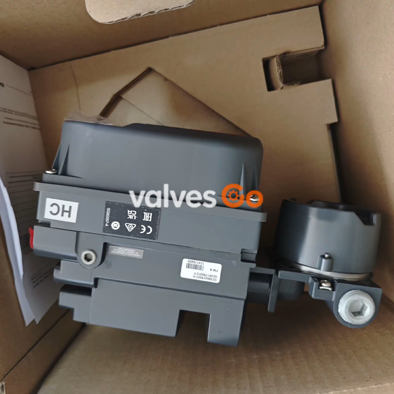
| PWB assembly | HW2 version, without travel feedback (HC level) | - | Industrial-grade electronic assembly |
| PWB assembly | HW2 version, with travel feedback (ODV level) | - | Supports partial stroke test function |
| Pneumatic relay assembly | Double-acting (Type A) | 38B5786X052 | Stainless steel body + engineering plastic seals |
| Pneumatic relay assembly | Single-acting direct (Type C) | 38B5786X132 | Low bleed design |
| Pneumatic relay assembly | Single-acting reverse (Type B) | 38B5786X092 | Factory pre-calibrated, no field adjustment required |
| Terminal box kit | Aluminum, standard, without travel feedback | 19B5401X142 | IP66 protection rating |
| Terminal box kit | Stainless steel, extreme temp, with travel feedback | 19B5401X202 | For hazardous areas and low temperature conditions |
| Pressure gauge | Double-acting, PSI/bar range (0-160PSI/11bar) | 47 | Vibration-resistant design, accuracy class 1.5 |
| Seals/O-rings | Standard conditions | 39/237 | Nitrile |
| Seals/O-rings | Extreme temperature | - | Fluorosilicone |
Petrochemical, power generation, water treatment, food and beverage, pharmaceutical, metallurgy, and other industrial process control fields, especially suitable for critical process loops requiring precise valve position control, remote diagnostics, and preventive maintenance.
Explore similar products in our catalog