Up to 99.8% Efficiency

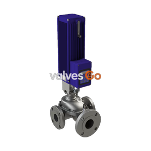
BURKERT 329197 (Type 3280) is an electromotive 2-way globe proportional valve with a brass body, 1/2" NPT ports, DN10 seat, EPDM seal, 0–6 bar range, and 4–20 mA setpoint control.
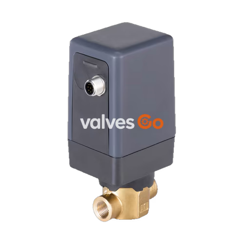
BURKERT 329197 (Type 3280) is an electromotive 2-way globe proportional control valve designed for metering and continuous flow regulation of neutral liquids and gases in open and closed loops. Driven by a linear stepper motor coupled directly to a threaded spindle and control cone, the unit executes positioning without external driver cards. The actuator draws less than 1 W in holding mode once the targeted stroke position is achieved, providing low operating electrical consumption across duty cycles up to 100%.
Configuration 329197 features a brass valve body with 1/2" NPT female process connections, a DN10 nominal orifice, and an EPDM seat seal. Flow passes under the valve seat, closing against the process fluid flow. Positioning relies on a continuous 4–20 mA analog input signal, and an active PNP digital output provides positive feedback whenever the valve reaches the fully closed position.
| Parameter | Specification |
|---|---|
| Valve Design | Electromotive 2-way seat valve (Type 3280) |
| Article Number (Ident) | 329197 |
| Orifice Size (Nominal Seat Diameter) | DN10 (10 mm / 3/8") |
| Port Connection | 1/2" NPT (ASME B1.20.1) internal thread |
| Valve Body Material | Brass |
| Seat Seal Material | EPDM (Ethylene-propylene-diene rubber) |
| Stem Seal Material | EPDM |
| Flow Direction | Under seat (closes against flow direction) |
| Flow Coefficient (Kvs) | 1.9 m³/h (water at +20 °C, Δp = 1 bar) |
| Operating Pressure Range | 0 to 6 bar(g) |
| Fluid Media | Neutral gases and liquids |
| Max. Viscosity | Up to 600 mm²/s (cSt) |
| Medium Temperature Range | 0 °C to +70 °C (EPDM material limits -30 °C to +70 °C) |
| Ambient Temperature Range | -10 °C to +50 °C (standard DN1 to DN6 up to +60 °C; DN8/10 restricted to +50 °C) |
| Operating Voltage | 24 V DC ±10% (max. residual ripple 10%) |
| Power Consumption | Standby: < 1 W; Operating: max. 12 W (DN8/DN10) |
| Actuating Time (0–100%) | Approx. 2.5 s (normal mode) / 5.0 s (slow mode) |
| Position Control Dead Band | ±0.5% (span 1:100) |
| Setpoint Input | 4–20 mA (switchable to 0–10 V via DIP switch 2) |
| Digital Output | PNP active, max. 100 mA current limit (valve closed feedback) |
| Electrical Connection | M12 circular connector, 8-pole, A-coded |
| Protection Class | IP54 (with matching mating connector attached) |
| Installation Position | Any orientation; preferably with actuator upright |
Type 3280 standard valves operate over the 0 to 6 bar pressure range across seat diameters from DN1 to DN10:
| Function | Seat Diameter (mm) | Standard Port Size | Kvs Value [m³/h] | Operating Pressure Range [bar(g)] |
|---|---|---|---|---|
| Proportional Control | 1 | G 1/4 | 0.030 | 0 to 6 |
| Proportional Control | 1.5 | G 1/4 | 0.065 | 0 to 6 |
| Proportional Control | 2 | G 1/4 | 0.130 | 0 to 6 |
| Proportional Control | 3 | G 1/4 | 0.300 | 0 to 6 |
| Proportional Control | 4 | G 3/8 | 0.500 | 0 to 6 |
| Proportional Control | 5 | G 3/8 | 0.750 | 0 to 6 |
| Proportional Control | 6 | G 3/8 | 0.900 | 0 to 6 |
| Proportional Control | 8 | G 1/2 | 1.500 | 0 to 6 |
| Proportional Control (329197) | 10 | G 1/2 / NPT 1/2 | 1.900 | 0 to 6 |
INFO
For article 329197, the port connection is 1/2" NPT internal thread with a DN10 orifice diameter and a rated Kvs of 1.9 m³/h.
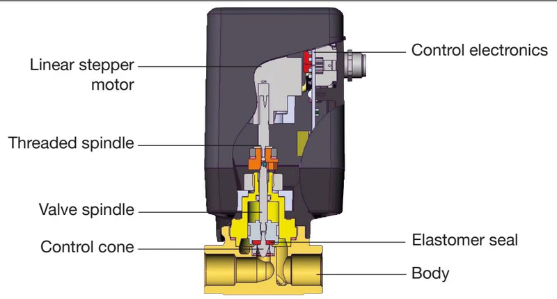
The electromotive actuator is completely isolated from process fluid contact.
| Item | Component | Material (Configuration 329197) | Alternate Material Options |
|---|---|---|---|
| 1 | Actuator Housing Cover | Polycarbonate (PC GF10) | — |
| 2 | Actuator Lower Housing | Polyphenylene sulphide (PPS GF40) | — |
| 3 | Stem Seal | EPDM | FKM, NBR |
| 4 | Valve Stem | Stainless steel 1.4305 | — |
| 5 | Upper Body / Bonnet | Brass | Stainless steel 1.4305 |
| 6 | Guided Piston with Control Cone | PTFE / Stainless steel 1.4305 | — |
| 7 | Resilient Seat Seal | EPDM | FKM, NBR, PEEK (DN1/1.5) |
| 8 | O-Rings | EPDM | FKM, NBR |
| 9 | Valve Seat | Stainless steel 1.4301 / 1.4305 | — |
| 10 | Valve Body | Brass | Stainless steel AISI 316L |
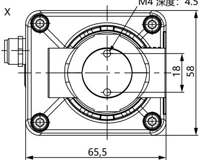
| Port Thread D | A (mm) | B (mm) | C (mm) | E (mm) | F (mm) | G (mm) | H (mm) |
|---|---|---|---|---|---|---|---|
| G 1/4 | — | — | 12 | 96.4 | 134.2 | 10 | 27.5 |
| NPT 1/4 | 5.8 | 10.0 | — | 96.4 | 134.2 | 10 | 27.5 |
| G 3/8 | — | — | 12 | 97.4 | 137.2 | 12 | 27.5 |
| NPT 3/8 | 6.0 | 10.3 | — | 97.4 | 137.2 | 12 | 27.5 |
| G 1/2 | — | — | 14 | 97.4 | 139.2 | 14 | 29.5 |
| NPT 1/2 (329197) | 8.2 | 13.7 | — | 97.4 | 139.2 | 14 | 29.5 |
Fixing threads on bottom of body: M4 with 4.5 mm thread depth. Total unit weight with stainless steel body is approximately 0.7 kg.
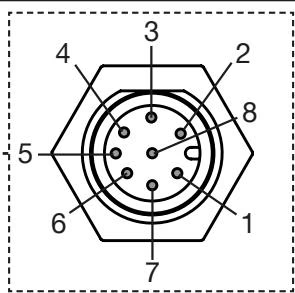
BURKERT 329197 uses an integrated 8-pole M12 A-coded male connector. None of the electrical inputs or outputs are galvanically isolated from the 24 V DC supply voltage. The threaded metal sleeve of the connector connects internally to the body for EMC earthing.
| Pin | Core Color (Cable 919061) | Configuration | External Circuit / Signal Details |
|---|---|---|---|
| 1 | White | Supply + | 24 V DC ±10%, max. residual ripple 10% |
| 2 | Brown | Supply GND | 24 V DC GND |
| 3 | Green | Do not connect | Electrically isolate wire on connection cable |
| 4 | Yellow | Do not connect | Electrically isolate wire on connection cable |
| 5 | Grey | Do not connect | Electrically isolate wire on connection cable |
| 6 | Pink | Setpoint value input + | 4–20 mA (or 0–10 V), not galvanically isolated |
| 7 | Blue | Digital output | PNP active (0/24 V), max. 100 mA current limit; logic 1 (10–30 V) when valve is closed |
| 8 | Red | Signal GND | Signal GND |
| Body | Shielding | Cable shield | Connect to earthing point via short, large-cross-section lead |
WARNING
Do not connect pins 3, 4, or 5 on standard control valve models. Ensure loose wire ends in accessory cables are insulated to prevent control board damage.
Standard control valve parameters can be adjusted via 4 DIP switches located on the internal control PCB under the actuator housing cover:
| DIP Switch | Position | Function on Standard Control Valve |
|---|---|---|
| 1 | OFF | Normal operating direction: increasing setpoint (4 to 20 mA) opens the valve (0 to 100%) |
| 1 | ON | Inverted operating direction: decreasing setpoint (20 to 4 mA) opens the valve (0 to 100%) |
| 2 | OFF | Setpoint input calibrated for 4 to 20 mA current signal |
| 2 | ON | Setpoint input calibrated for 0 to 10 V voltage signal |
| 3 | OFF | Actuating speed normal mode: approx. 2.5 s for 0 to 100% stroke |
| 3 | ON | Actuating speed slow mode: approx. 5.0 s for 0 to 100% stroke |
| 4 | OFF | Low power function disabled (full actuator torque) |
| 4 | ON | Low power function enabled: reduced motor current and heat generation; restricted to max. 3 bar medium pressure and max. 1 bar differential pressure |
Actuator Cover Removal and Tightening
To access DIP switches, isolate the power supply, loosen the four non-losable housing screws, and support the lower connection plate so it does not drop. When reassembling, verify that internal wires are not pinched and tighten screws to 2 Nm.
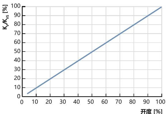
Type 3280 maintains a linear flow characteristic across its positioning stroke. Proper orifice sizing ensures that the valve retains controllability without turning the linear valve curve into a distorted system characteristic.
$$\Delta p_{\text{valve}} > 25% \text{ of total system pressure drop}$$
| Pressure Drop State | Liquid Medium (Kv in m³/h) | Gaseous Medium (Kv in m³/h) |
|---|---|---|
| Subcritical ($p_2 > \frac{p_1}{2}$) | $K_v = Q \sqrt{\frac{\rho}{1000 \Delta p}}$ | $K_v = \frac{Q_N}{514} \sqrt{\frac{T_1 \rho_N}{p_2 \Delta p}}$ |
| Supercritical ($p_2 < \frac{p_1}{2}$) | $K_v = Q \sqrt{\frac{\rho}{1000 \Delta p}}$ | $K_v = \frac{Q_N}{257 p_1} \sqrt{T_1 \rho_N}$ |
Where $Q$ is liquid volume flow in m³/h, $Q_N$ is gas flow in m³N/h at standard conditions (+0 °C, 1.013 bar), $p_1$ is inlet pressure in bar absolute, $p_2$ is outlet pressure in bar absolute, $\Delta p = p_1 - p_2$, $\rho$ is liquid density in kg/m³, $\rho_N$ is gas standard density in kg/m³, and $T_1$ is temperature in Kelvin (273 + t).
An integrated LED indicator on the actuator housing communicates operational status:
| LED Color | State | Operating Meaning |
|---|---|---|
| White | Continuously lit | Normal operating mode |
| Yellow | Continuously lit | Valve is fully open (100% stroke) |
| Yellow | Flashing (alternating) | Out of specification: ambient or fluid conditions outside allowable limits |
| Green | Continuously lit | Valve is fully closed (0% stroke) |
| Red | Flashing | Error detected (signal < 4 mA, excessive voltage ripple, overtemperature, or motor stall) |
| Orange | Flashing | Function check in progress |
| LED Off | Off | Power supply disconnected or absent |
Zero-Point Shut-Off Function
Type 3280 incorporates a tight zero-point shut-off. If the analog input signal falls below 1% of the configured range (< 4.16 mA), the motor drives the control cone firmly into the seat to achieve zero leakage. If the signal drops below 4.0 mA, the unit interprets this as a cable break and flashes the red LED.
In standard configuration, Type 3280 holds its current position upon power interruption. When automatic closure or opening on power loss is required, an optional external Type 1573 capacitive buffer module (Ident 773440) provides backup energy.
Upon utility power interruption, the buffer module delivers an 18 V DC auxiliary voltage for several seconds. The valve electronics detect the voltage step-down and drive the actuator to the predetermined safety position (factory default: Valve Closed; inverted direction on DIP 1 results in Valve Open). A single buffer module can power up to three Type 3280 valves.
| Article / Ident | Valve Type | Body Material | Port Size | Orifice | Seal | Voltage | Control Mode |
|---|---|---|---|---|---|---|---|
| 329197 | 3280 | Brass | 1/2" NPT female | DN10 | EPDM | 24 V DC | 4–20 mA analog input, valve closed digital output |
| Accessory Description | Specification | Order Number (Ident) |
|---|---|---|
| M12 Female Cable Connector | 8-pole, unshielded, 2 m pre-wired cable | 919061 |
| M12 Female Cable Connector | 8-pole, shielded, 2 m pre-wired cable | 918991 |
| Capacitive Buffer Module | Type 1573, DIN-rail mount, provides backup power for failsafe positioning | 773440 |
| Power Supply Phoenix Class 2 | Type 1573, 85–240 V AC to 24 V DC, 1.25 A (UL 1310) | 772438 |
| DIN-Rail Power Supply | Type 1573, 100–240 V AC to 24 V DC, 1 A (UL 1310) | 772361 |
| DIN-Rail Power Supply | Type 1573, 100–240 V AC to 24 V DC, 2 A (UL 1310) | 772362 |
| DIN-Rail Power Supply | Type 1573, 100–240 V AC to 24 V DC, 3.8 A (UL 60950-1) | 772898 |
Explore similar products in our catalog