

PN16

BURKERT 325990 Type 6407 servo-assisted normally closed 2/2-way piston valve features a G 3/4 brass body, stainless steel seat, 0 to 10 bar range, and 110 V 60 Hz AC coil.
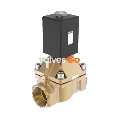
BURKERT 325990 is a Type 6407 servo-assisted 2/2-way piston valve configured with circuit function A (normally closed), an internal thread G 3/4 process port, and a DN 20 nominal orifice. The valve employs a rigid mechanical coupling between the pilot valve plunger and the main piston, enabling full opening without any minimum differential pressure across the 0 to 10 bar operating span. Built with a brass valve body, a stainless steel seat insert, and a PTFE/graphite sealing combination, article 325990 is designed for neutral gases, liquids, and steam within a fluid temperature range of -40 °C to +150 °C.
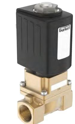
The electromagnetic actuation system utilizes a 42 mm epoxy-encapsulated coil (Class H thermal insulation) rated for 110 V AC at 60 Hz. The welded connection between the core guide tube and the stopper provides pressure containment and leak tightness. When paired with an approved DIN EN 175301-803 Form A cable connector, the assembly achieves an IP65 ingress protection rating.
Article 325990 operates according to circuit function A as a 2/2-way normally closed valve with fluid inlet at port 1 (P/NC) and flow directed above the seat.
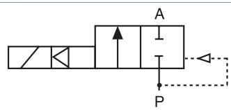
Circuit Function A Details
In the de-energized state, spring force and medium pressure act on the piston to seal the main orifice shut. When the solenoid coil is energized, the plunger lifts and unseats the pilot orifice while mechanically pulling the piston upward through the fixed coupling. This mechanism allows the valve to open fully even at 0 bar differential pressure.
| Specification Parameter | Value / Description |
|---|---|
| Valve Type | 6407 |
| Article Number | 325990 |
| Circuit Function | CF A (2/2-way, normally closed) |
| Port Connection | G 3/4 internal thread |
| Nominal Orifice | DN 20 (20 mm) |
| Pressure Range | 0.00...10.00 bar (0...1.0 MPa) |
| Flow Rate Kv (Water) | 5.7 m³/h (measured at +20 °C, 1 bar delta-P) |
| Flow Rate QNn (Gas) | 6100 l/min |
| Operating Voltage | 110 V AC (60 Hz) |
| Voltage Tolerance | ±10% |
| Coil Size | 42 mm (Size K) |
| Inrush Power (AC) | 150 VA |
| Holding Power (AC) | 41 VA / 16 W |
| Duty Cycle | 100% continuous operation |
| Switching Time (Opening) | 30 ms (measured at +20 °C, 6 bar) |
| Switching Time (Closing) | 250 ms (measured at +20 °C, 6 bar) |
| Fluid Viscosity | Max. 21 mm²/s (21 cSt) |
| Medium Temperature | -40 °C...+150 °C |
| Ambient Temperature | Max. +45 °C |
| Body Material | Brass |
| Seat Material | Stainless steel |
| Seat Seal / Outside Seal | PTFE / Graphite |
| Electrical Connection Sort | Plug pattern Form A acc. to DIN EN 175301-803 |
| Protection Class | IP65 with mounted cable plug |
| Overall Face-to-Face Length | 100 mm |
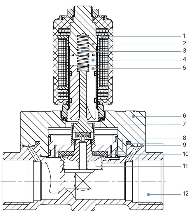
| Item No. | Element | Material Designation |
|---|---|---|
| 1 | Coil | Epoxy |
| 2 | Stopper | Stainless steel 1.4113 / AISI 434 |
| 3 | Spring | Stainless steel 1.4310 / AISI 301 |
| 4 | Armature guide tube | Stainless steel 1.4303 / AISI 305 / 308 |
| 5 | Core (Armature) | Stainless steel 1.4113 / AISI 434 |
| 6 | Cover | Brass |
| 7 | Seal | PTFE |
| 8 | Piston ring | PTFE |
| 9 | Sealing ring | Graphite |
| 10 | Plunger | Brass |
| 11 | Piston seal | PTFE |
| 12 | Valve body | Brass (seat in stainless steel) |
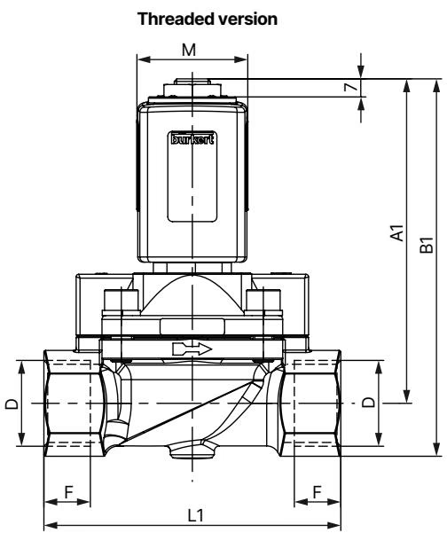
Dimensions for Type 6407 standard brass threaded body variants DN 13 through DN 32:
| DN | Port Thread | A1 [mm] | B1 [mm] | Thread Depth F1 [mm] | Body Width E1 [mm] | Length L1 [mm] | Wrench Size SW [mm] |
|---|---|---|---|---|---|---|---|
| 13 | G 1/2 | 118.7 | 132.7 | 14.0 | 40 | 65 | 27 |
| 20 (325990) | G 3/4 | 119.7 | 135.7 | 16.0 | 60 | 100 | 32 |
| 25 | G 1 | 125.7 | 146.2 | 18.0 | 70 | 115 | 41 |
| 32 | G 1 1/4 | 142.7 | 167.7 | 20.0 | 85 | 126 | 50 |
| 32 | G 1 1/2 | 146.7 | 176.7 | 22.0 | 85 | 126 | 60 |
Coil dimensions for Size K (42 mm width, standard on DN 20 AC):
Piping Cleanliness and Protection
Before piping installation, clean all connecting lines of scale and debris. Install a dirt trap upstream of the valve inlet with a mesh size of ≤ 500 µm to protect internal orifices and pilot passages from clogging.

Electrical Safety
Disconnect electrical power before connecting wiring or dismounting components. Secure the main circuit against unintentional reactivation. Always attach the protective grounding conductor (PE) and check continuity between the solenoid coil and the valve body.
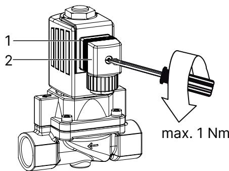
When securing the cable plug to the terminal prongs, tighten the center fastening screw to a maximum torque of 1 Nm to preserve the seal compression without stripping threads.
Solenoid Operation Precaution
Never energize the solenoid coil unless it is fully installed on the armature guide tube. Powering an unmounted coil causes rapid overheating and coil burnout.
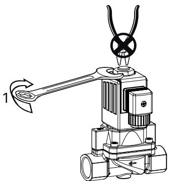
When reinstalling the coil on the core tube, position the coil over the tube until firmly seated against the valve cover, then torque the retention nut with an open-end wrench. Do not continue turning the nut once specified torque is reached, as loosening a firmly fastened nut can cause media leakage.
| Component Connection | Nominal Size (DN) | Tightening Torque |
|---|---|---|
| Solenoid fixing nut | DN 13...32 | 15 Nm |
| Solenoid fixing nut | DN 50 | 19 Nm |
| Valve cover screws | DN 13 | 3.0...4.0 Nm |
| Valve cover screws (325990) | DN 20 | 6.0...7.0 Nm |
| Valve cover screws | DN 25 / 32 | 8.0...10.0 Nm |
| Valve cover screws | DN 50 | 13.0...17.0 Nm |
| Stopper with armature tube | DN 13...32 | 49.0...51.0 Nm |
| Stopper with armature tube | DN 50 | 110.0...115.0 Nm |
| Cable plug center screw | Form A | Max. 1 Nm |
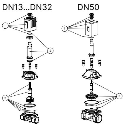
Original replacement parts available for maintenance comprise:
When ordering replacement assemblies, specify the spare part item number alongside the valve article number 325990.
Cable plugs conforming to DIN EN 175301-803 Form A are available separately for electrical interface:
| Accessory Type | Circuit Configuration | Voltage Range | Article Number |
|---|---|---|---|
| Type 2518 | Without circuitry | 0...250 V AC/DC | 314802 |
| Type 2518 | With LED indicator | 12...24 V AC/DC | 314812 |
| Type 2518 | With LED and varistor | 12...24 V AC/DC | 314820 |
| Type 2518 | With rectifier, LED, and varistor | 12...24 V AC/DC | 314816 |
| Type 2509 | Standard Form A without wiring | 0...250 V AC/DC | 137943 |
Explore similar products in our catalog


