Type 2032

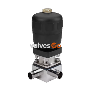
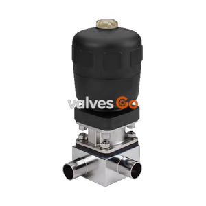
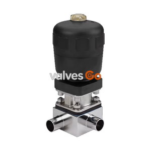
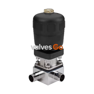
Burkert Type 2935 (SKU 20142411) manually operated tank bottom diaphragm valve. Features DN 65 flange connection, PTFE/EPDM diaphragm, and stainless steel block body for hygienic applications.
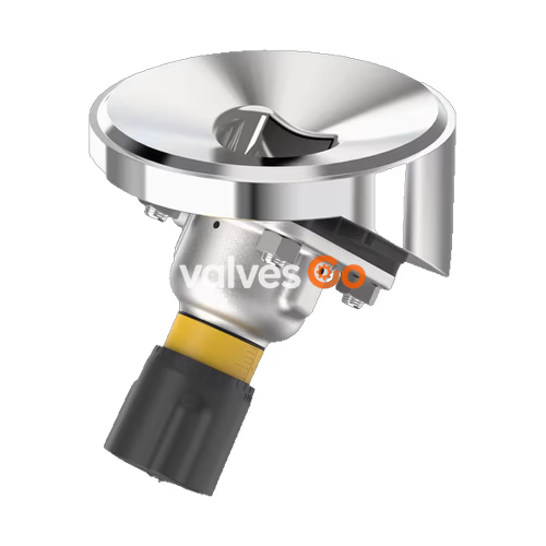
The BURKERT Type 2935 manually operated diaphragm valve consists of a manually operated actuator, a diaphragm, and a tank bottom valve body. The manual actuator with a plastic or stainless steel handwheel is available with a diaphragm bonnet made of stainless steel or plastic, ensuring reliable use in hygienic or aggressive ambient conditions. The flow-optimized tank bottom valve body features minimum dead space, enabling high flow values and a wide range of possible applications. The actuator has a compact, autoclavable design and is equipped with an integrated visual position indicator, a reproducible stroke scale, and an adjustable closing limiter.
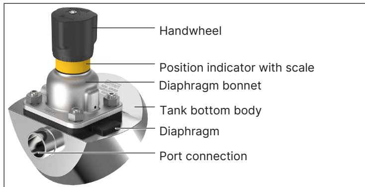
| Product Properties | Description |
|---|---|
| Block body material | Stainless steel block material 1.4435 according to DIN EN 10088 and 316L according to ASME BPE |
| Diaphragm material | PTFE with EPDM backing membrane (SKU 20142411); EPDM, advanced PTFE/EPDM, GYLON®/EPDM also available |
| Actuator material | Stainless steel/PPS, PPS/PPS, stainless steel/stainless steel |
| Standard surface quality | Internally electrically polished: Ra ≤ 0.38 μm (ASME BPE SF4/DIN HE4); Internally mechanically polished: Ra ≤ 0.5 μm (ASME BPE SF1) |
| Medium temperature | -10...+130 °C (PTFE/EPDM); steam sterilisation +140 °C for 60 min |
| Ambient temperature | -10...+130 °C (short-term up to +150 °C), autoclavable |
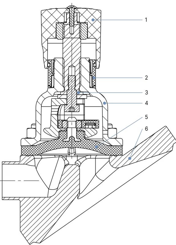
| No. | Element | Material |
|---|---|---|
| 1 | Handwheel | Polyphenylene sulphide (PPS), stainless steel 1.4308 |
| 2 | Visual position indicator | Polyamide (PA), stainless steel 1.4305 |
| 3 | Valve spindle | Stainless steel 1.4305 |
| 4 | Diaphragm bonnet | Stainless steel 1.4308, polyphenylene sulphide (PPS) |
| 5 | Diaphragm | PTFE/EPDM (EA), EPDM (AD), advanced PTFE/EPDM (EU), laminate of GYLON® and EPDM (ER) |
| 6 | Valve body | Stainless steel block material |
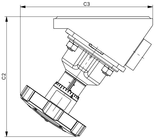
| Diaphragm size | C2 (mm) | C3 (mm) |
|---|---|---|
| 15 | 103 | 101 |
| 20 | 116 | 115 |
| 25 | 127 | 129 |
| 40 | 182 | 201 |
| 50 | 203 | 217 |
| 65 | 265 | 305 |
| 80 | 336 | 278 |
| 100 | 300 | 370 |
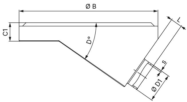
(Dimensions in mm. Refer to the full datasheet for comprehensive size charts across all standards including DIN EN ISO 1127, ASME BPE, and SMS 3008).
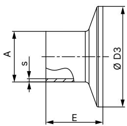
INFO
Clamp dimensions must be added to the welded connection dimensions.
DANGER
Risk of injury due to high pressure and escaping medium. Switch off the pressure before working on the device or system. Vent or empty the lines.
Recommendations for welding:
WARNING
To prevent damage, dismantle the actuator and diaphragm before welding the valve body. Only use welding materials which are suitable for the tank bottom body.
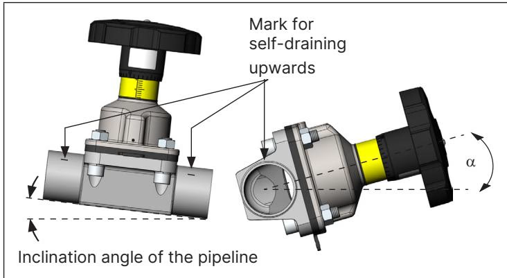
It is the responsibility of the installer and the operator to ensure self-draining. The self-draining angle (α) depends on the valve body size and the inner diameter of the port connection. The marking on the port connection of the valve body serves as an orientation aid and must point upwards.
When installing the device, tighten each fastening screw in 3 stages (approx. 1/3, approx. 2/3, 3/3 of the tightening torque) crosswise. The diaphragm should be positioned and pressed evenly all around the actuator and valve body.
| Diaphragm size | Tightening torque for PTFE / advanced PTFE / GYLON® (Nm) |
|---|---|
| 15 | 4 |
| 25 | 6 |
| 40 | 10 |
| 50 | 15 |
| 65 | 30 |
| 80 | 40 |
(A tolerance of +10 % of the respective tightening torque applies to all values).
When used in accordance with the operating instructions, the actuator of the diaphragm valve is maintenance-free.
Inspection intervals:
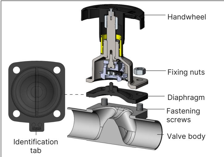
The diaphragm is attached via a bayonet catch (sizes 15-100 for PTFE) or a threaded connection (sizes 25-100 for EPDM/FKM).
TIP
For diaphragms with threaded connection: First screw on the diaphragm hand-tight, then loosen it by one-half turn anticlockwise to prevent damage due to an energised pin.
WARNING
For diaphragms with a bayonet catch: If the insert is not removed when switching from EPDM to PTFE, a diaphragm with a bayonet catch can still be fitted, which can severely damage the diaphragm and valve body.
Explore similar products in our catalog