

PN16

BURKERT 20135147 (Type 8652) is a 24-slot AirLINE valve island featuring 16x 5/2-way CF-H valves, 8 blind plates, 48 DI channels, Industrial Ethernet RJ45, and an aluminum AirLINE Quick base for cabinet mounting.
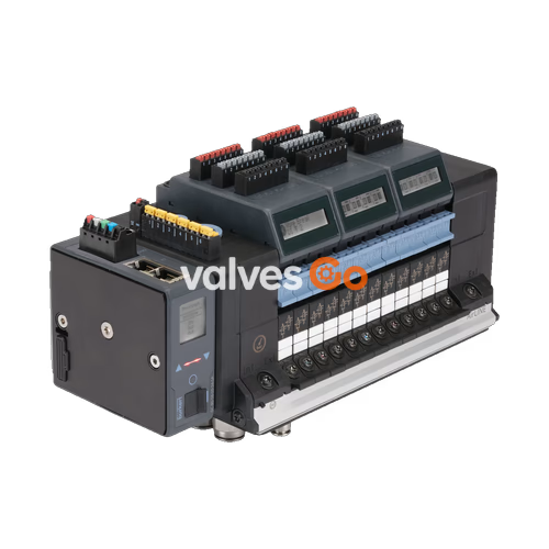
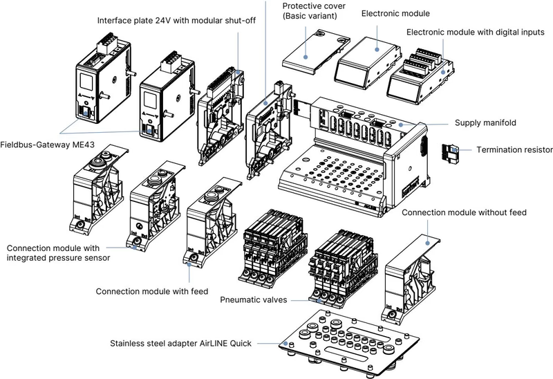
BURKERT 20135147 is a pre-configured 24-station execution of the Type 8652 AirLINE valve island platform, built for process automation enclosures. This unit integrates sixteen 5/2-way monostable pilot valves (Circuit Function H) at positions 1 through 16 and eight blanking plates at positions 17 through 24. It combines an anodized aluminium AirLINE Quick base plate, an integrated pneumatic intermediate feed module, 48 digital input channels distributed across six 8DI electronic modules, and a dual-port Industrial Ethernet interface (RJ45).
Process safety features include integrated check valves inside exhaust channels 3 (R) and 5 (S) to isolate unvented pressure spikes from back-actuating adjacent actuators. Channel 1 (P) features pneumatic HotSwap isolation, enabling single-valve replacement while main air pressure remains applied to the manifold without disrupting adjacent active channels.

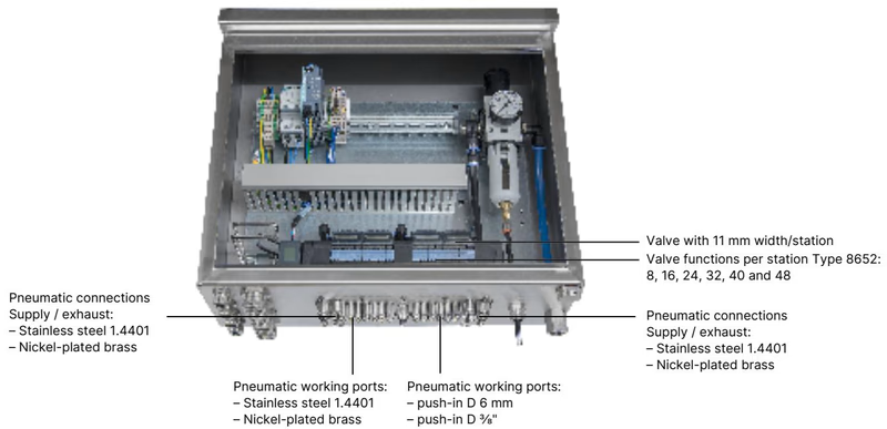
The AirLINE Quick adapter interface attaches directly into cutouts at the base or wall of the control cabinet. All primary air feed lines and cylinder working ports pass directly through the cabinet floor, eliminating bulkhead connectors and cabinet-internal tubing harness routing.
| Component | Specification |
|---|---|
| Adapter Plate Material | Anodized aluminium (1.4301 stainless steel optional in series) |
| Pneumatic Fitting Material | Nickel-plated brass (D10 supply, D6 working) |
| Supply / Exhaust Ports | Push-in connector D10 mm (3/8" compatible) |
| Working Ports | Push-in connector D6 mm (1/4" compatible) |
| Auxiliary Pilot Air | Internal feed (no external pilot tubing required) |
| Mounting Location | Control cabinet floor or control cabinet wall |
| Technical Parameter | Specified Value |
|---|---|
| Nominal Pressure Range | Vacuum to 10 bar (-1.00 bar to 10.00 bar) |
| Pilot Control Pressure | 3.00 bar to 10.00 bar |
| Nominal Flow Rate $Q_{Nn}$ (Air) | 310 l/min (measured at +20 °C, 6 bar inlet, 1 bar pressure drop) |
| Hot Swap Flow Impact | Flow rate reduced by approx. 3% through internal check seats |
| Operating Medium | Lubricated or oil-free dry compressed air, neutral gases |
| Compressed Air Quality | ISO 8573-1:2010, Class 7.4.4 (5 µm pre-filter recommended) |
| Operating Voltage | 24 V DC (±10%), residual ripple 1 Vss |
| Valve Coil Power Rating | 0.7 W nominal inrush; 0.175 W holding after electronic power drop |
| Valve Coil Current Rating | 29 mA nominal; 10 mA holding after power reduction |
| Duty Cycle | Continuous operation (100% ED) |
| Electrical Protection Class | Class III according to DIN EN 61140, VDE 0140 |
| Degree of Protection | IP20 unhoused; IP65 mounted in closed cabinet with AirLINE Quick |
| Type Rating (NEMA 250) | Type 4X in closed enclosures (stainless steel variants) |
| Ambient & Medium Temperature | -10 °C to +55 °C |
| Storage Temperature | -20 °C to +60 °C |
Diagnostic Display
The integrated LC display presents diagnostic alarms, channel switching states, and system conditions in both clear text and graphical symbols. Messages are routed concurrently via the Industrial Ethernet protocol to the higher-level PLC.
Article 20135147 houses 16 active Type 6534 pilot solenoid valves and 8 blanking dummy plates, occupying the 24 available station slots.
| Slot Allocation | Installed Component | Circuit Function | Nominal Diameter | Switching Time (Open / Close) |
|---|---|---|---|---|
| Slots 1–16 | Type 6534 Solenoid Valve | CF-H (5/2-way monostable, servo-controlled, manual override) | 4 mm | 20 ms / 25 ms |
| Slots 17–24 | Dummy Valve Plate | Blind closure for future expansion | — | — |
CF-H Operation: Pressure applied at supply port 1 channels pilot air to energize the spool, directing pressure to working port 2 or working port 4 depending on coil excitation state.
Article 20135147 includes one intermediate air feed module positioned within the valve train to maintain pneumatic replenishment across all 24 stations.
| Dimension Code | Description | Value (mm) |
|---|---|---|
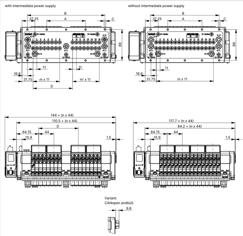
| A | Mounting pitch dimension 1 | 156 mm |
| B | Mounting pitch dimension 2 | 312 mm |
| C | Screw fixing pattern | 10 × M5 |
| D | Intermediate supply module offset | 158.3 mm |
| m | Left valve bank segment width | 11 stations (11 mm pitch per station) |
| m' | Right valve bank segment width | 11 stations (11 mm pitch per station) |
| n | Number of base module sub-blocks | 6 blocks |
| Station Pitch | Width per single valve slot | 11 mm |
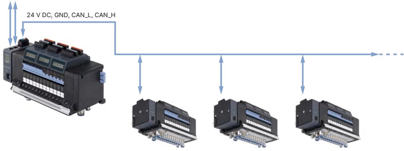
Power feeds for the digital logic and pneumatic solenoid coils are physically isolated to prevent coil switching noise from disrupting communications.
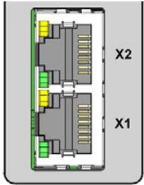
| Pin | RJ45 Signal Assignment |
|---|---|
| 1 | TX+ |
| 2 | TX- |
| 3 | RX+ |
| 4 | Not connected (N.C.) |
| 5 | Not connected (N.C.) |
| 6 | RX- |
| 7 | Not connected (N.C.) |
| 8 | Not connected (N.C.) |
Supported Ethernet protocols on ports X1/X2: PROFINET IO, EtherNet/IP, Modbus TCP, EtherCAT, CC-Link IE Field Basic.
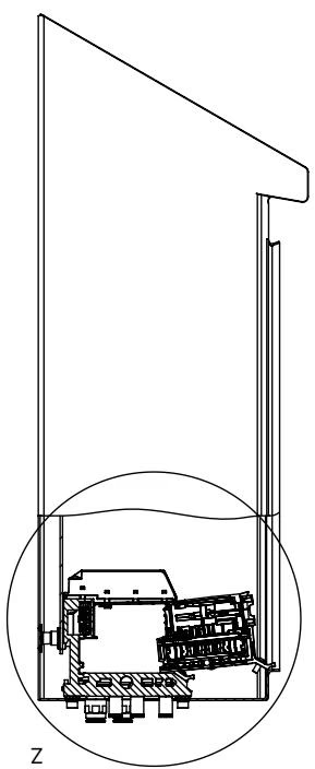
When mounting the island inside a control cabinet, clearance dimensions to enclosure walls and door front edges must be respected to operate the Hot Swap locking levers.
Hot Swap Operation Rule
During pneumatic Hot Swap, individual Type 6534 pilot valves can be unfastened and lifted from their station under line pressure up to 10 bar. Ensure the locking screws are backed out evenly and replacement units are aligned on the locating pins before torquing.
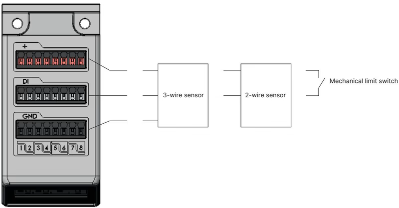
Article 20135147 incorporates six 8DI electronic modules, providing 48 discrete feedback channels directly on the valve manifold.
| Parameter | Specification |
|---|---|
| Sensor Supply Voltage | 24 V DC (via electronic module) |
| Sensor Current Limit | Max. 30 mA per digital input channel |
| Permissible Sensors | Commercial 3-wire sensors, 2-wire sensors (10–30 V), mechanical dry contacts |
| Switching Thresholds | $V_{\text{OFF}} = 0\text{ to }5\text{ V}$, $V_{\text{ON}} = 10\text{ to }30\text{ V}$ |
| Input Current at $V_{\text{ON}}$ | Max. 5.7 mA per channel (typical 24 V DC) |
| Input Impedance | $> 4\text{ k}\Omega$ |
| Galvanic Isolation | None (common reference potential across all channels) |
| Permissible Wire Gauge | Conductor cross-section $\le 1.5\text{ mm}^2$ |
| Maximum Cable Run | $< 30\text{ m}$ |
| Diagnostic Condition | 3-Wire Sensor | 2-Wire Sensor | Mechanical Limit Switch | | :--- | :---: | :---: | :---: | | | Sensor Actuated (ON) | Yes | Yes | Yes | | Sensor Unactuated (OFF) | Yes | Yes | Yes | | Short Circuit Detection | Yes | — | — | | Wire Break Detection | — | Yes | — |
Type 8652 carries international explosion-protection certifications for Zone 2 and Zone 22 applications:
Hazardous Area Installation Rules
| Item Description | Quantity / Variant | Order Article Number |
|---|---|---|
| Replacement Solenoid Valve Type 6534 (CF-H, 5/2-way) | 1 unit with mounting screws | 301376 (REF 296033) |
| Replacement Dummy Valve Plate | 1 unit with mounting screws | 335779 (REF 327614) |
| Electronic Display Module with Digital Inputs | 8DI spare module | 384872 |
| 5-Pin Spring-Loaded Terminal Block | Communication / display supply | 920180 |
| 2-Pin Spring-Loaded Terminal Block | Pneumatic valve auxiliary supply | 920442 |
| Fastening Screw Set M5 × 10 A2 DIN 6912 | Pack of 10 screws for cabinet base | 308661 |
| Height Adapter for 24-fold with Intermediate Feed | 1 unit | 754964 |
| Retaining Plate for 24-fold with Intermediate Feed | 1 unit (exterior cabinet wall) | 60005570 |
| Blanking Base Plate for 24-fold with Intermediate Feed | 1 unit | 754969 |
| USB-büS Interface Set 1 (Type 8923) | For Bürkert Communicator software connection | 772426 |
Explore similar products in our catalog


