Up to 99.8% Efficiency

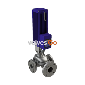
BURKERT 20122430 Type 3361 electromotive globe control valve features an AG2 1300 N actuator, G 1/2 stainless steel body, 6 mm seat orifice, Kv 1.25 m3/h, 24 V DC supply, PID controller, and SAFEPOS pack.
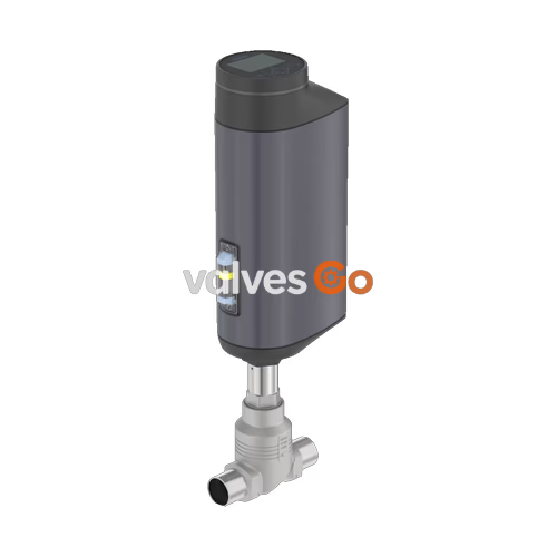
BURKERT 20122430 Type 3361 is an electromotive 2-way globe control valve engineered for continuous flow regulation in demanding industrial processes. Driven by an AG2 electromotive linear actuator generating 1,300 N nominal positioning force, this assembly combines a G 1/2 internal thread cast stainless steel body (CF3M), a 6 mm nominal seat orifice, and an equal-percentage regulating cone yielding a nominal Kv value of 1.25 m³/h (Cv 1.45 gal/min). The drive system pairs a brushless DC motor with a precision ball screw, delivering a linear positioning speed of 6 mm/s and a typical full-stroke closing time of 3.4 s (3,400 ms). It operates from a 24 V DC power supply and comes equipped with an integrated PID process controller, an illuminated 360° status display with operation keys, and an internal SAFEPOS energy-pack storage unit that automatically shifts the valve to a defined safety position upon supply interruption.
Flow passes beneath the valve seat (flow direction 2 → 1) to oppose closing forces and prevent water hammer. Pressure fluctuations in the line do not alter the valve position due to the non-backdriving mechanical drive train. The assembly complies with European Regulation (EC) 1935/2004 for wetted food contact surfaces and provides ingress protection to IP65/IP67 and NEMA 4X.
Component longevity in corrosive and industrial washdown environments is achieved through a material combination across the drive and fluidic sections.
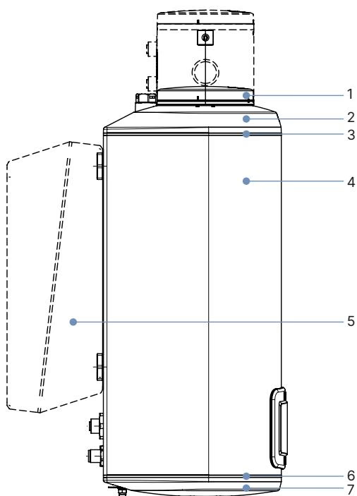
| Item | Component | Material |
|---|---|---|
| 1 | Display housing / blind cover | PPS (standard), stainless steel 1.4301 (ATEX/IECEx option) |
| 2 | Actuator cover | PPS |
| 3, 6 | Seals | EPDM |
| 4 | Actuator housing | Powder-coated aluminium |
| 7 | Actuator base | PPS |
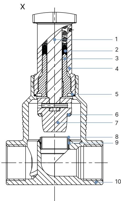
| Item | Component | Material |
|---|---|---|
| 1 | Spindle | Stainless steel 1.4401 (316) / 1.4404 (316L) |
| 2 | Spindle seal | PTFE V-rings (filled) with spring compensation |
| 3 | Spindle guide | Stainless steel 1.4404 (316L) |
| 4 | Packing gland tube | Stainless steel 1.4401 (316) |
| 5 | Valve body seal | Graphite or PTFE |
| 6 | Seat seal | Stainless steel 1.4571 |
| 7 | Control cone | Stainless steel 1.4571 |
| 8 | Valve seat | Stainless steel 1.4571 |
| 9 | O-ring valve seat | EPDM or PTFE |
| 10 | Valve body | Stainless steel CF3M |
Type 3361 with AG2 actuator uses a compact footprint suited to machine skid integration and piping manifolds.
| Nominal Diameter DN | NPS | H1 Standard Height (mm) | H2 Fieldbus Height (mm) |
|---|---|---|---|
| 10 | 3/8 | 417 | 489 |
| 15 | 1/2 | 417 | 489 |
| 20 | 3/4 | 423 | 495 |
| 25 | 1 | 446 | 518 |
| 32 | 1 1/4 | 474 | 546 |
| 40 | 1 1/2 | 479 | 551 |
| 50 | 2 | 485 | 557 |
INFO
Height values represent dimensions without sealing function. In the fully closed position, the actuator spindle raises by approximately 2 mm.
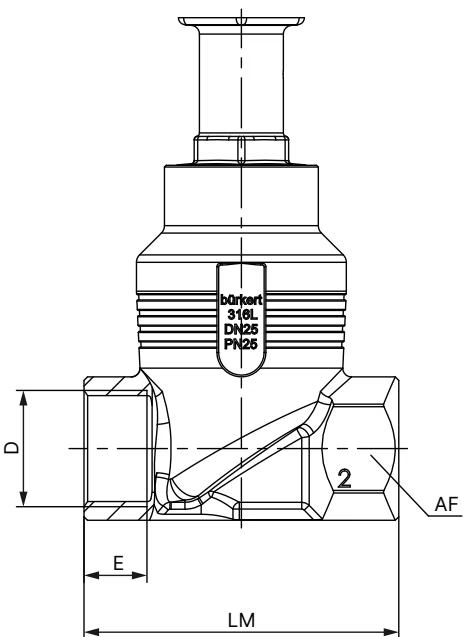
| DN | NPS | Thread D | Thread Depth E (mm) | Face-to-Face LM (mm) | Hex Flat AF (mm) |
|---|---|---|---|---|---|
| 10 | 3/8 | G 3/8 | 12 | 65 | 27 |
| 15 | 1/2 | G 1/2 | 14 | 65 | 27 |
| 20 | 3/4 | G 3/4 | 16 | 75 | 34 |
| 25 | 1 | G 1 | 18 | 90 | 41 |
| 32 | 1 1/4 | G 1 1/4 | 20 | 110 | 50 |
| 40 | 1 1/2 | G 1 1/2 | 22 | 120 | 55 |
| 50 | 2 | G 2 | 24 | 150 | 70 |
For article 20122430 (DN 15, G 1/2), overall height H1 is 417 mm, face-to-face length LM is 65 mm, internal thread depth E is 14 mm, and body hex width AF is 27 mm.
The equal-percentage control cone provides precise low-flow throttling over an extended travel range with a 50:1 theoretical rangeability.
| Stroke Percentage | Kv Value (m³/h) |
|---|---|
| 5% | — |
| 10% | 0.007 |
| 20% | 0.011 |
| 30% | 0.045 |
| 40% | 0.085 |
| 50% | 0.16 |
| 60% | 0.26 |
| 70% | 0.41 |
| 80% | 0.65 |
| 90% | 1.10 |
| 100% (Kvs) | 1.25 |
Operating pressure for the 6 mm seat with an AG2 (1,300 N) actuator reaches 25 bar(g) under seat leakage Class IV (metal seal). For process fluids with high solids or cavitation risks, hardened stainless steel trims extend service life.
Operating Temperature Derating
Permissible ambient temperature depends directly on process medium temperature. On AG2 units fitted with display modules and SAFEPOS energy-packs, ambient temperature must not exceed +55 °C when medium temperature reaches +140 °C, and derates further at higher process temperatures up to +185 °C.
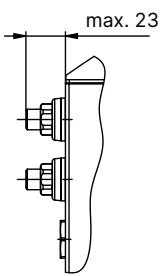
Electrical interface on article 20122430 uses three M12 circular connectors located on the side of the AG2 actuator base.
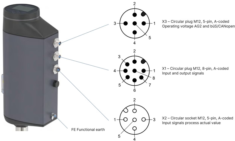
| Pin | X1 (8-Pin Male, A-Coded) | X2 (5-Pin Female, A-Coded) | X3 (5-Pin Male, A-Coded) |
|---|---|---|---|
| 1 | Digital input + | Do not connect | CAN Shield |
| 2 | GND (digital I/O) | Do not connect | 24 V DC ± 10% |
| 3 | Digital output 2 + | Do not connect | GND / CAN_GND |
| 4 | Digital output 1 + | Process actual value (4..20 mA) | CAN_H |
| 5 | Analogue output - | Process actual value GND | CAN_L |
| 6 | Analogue output + | — | — |
| 7 | Set-point / Analogue in - | — | — |
| 8 | Set-point / Analogue in + | — | — |
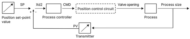
The internal PID controller calculates the valve position directly from the difference between the set-point value (CMD) and the transmitter feedback signal fed into X2 (such as flow from a Type 8098 FLOWave or pressure transmitter). Position feedback from the internal linear transducer maintains a position dead band within ±0.1%.
SAFEPOS Energy Pack
SAFEPOS energy-pack fully charges within 120 seconds of applying 24 V DC power. If power is severed, stored energy automatically drives the valve stem to the configured safety setting (normally closed in delivery status).
Routine maintenance involves checking the relief bore for leakage, replacing worn packing gland packages, and servicing the regulating cone or seat.
Operating State for Servicing
Prior to uncoupling the actuator from the valve body, switch the valve to MANUAL mode via the display or büS software, drive the stem to at least 1/3 open position, and disconnect electrical power.
| Connection Point | Thread / Size | Tightening Torque |
|---|---|---|
| Body connection to actuator | DN 10 / DN 15 | 45 ± 3 Nm |
| Screwed valve seat | DN 10 / DN 15 (Seats 3–15) | 20 + 3 Nm |
| Spindle guide (lower) | Spindle ø 10 mm (DN 10/15) | 15 Nm |
| Actuator base housing screws | M5 crosswise | 5 Nm |
| Manual override shaft | 3 mm Allen socket | Max. 2 Nm |
Pressure Relief
Depressurize and drain pipelines completely before dismounting the actuator. Never actuate the mechanical manual override under power or apply torques greater than 2 Nm to the mechanical override spindle.
After reassembling the body and actuator, connect 24 V DC power without line pressure and execute the X.TUNE calibration function via the display or Bürkert Communicator software to teach the physical stroke limits.
Explore similar products in our catalog