

PN16

Burkert 20120692 (Type 8647 AirLINE SP) is a 24-bank electro-pneumatic valve island with stainless steel AirLINE Quick base, HotSwap in P, integrated check valves, and Siemens ET 200SP integration.
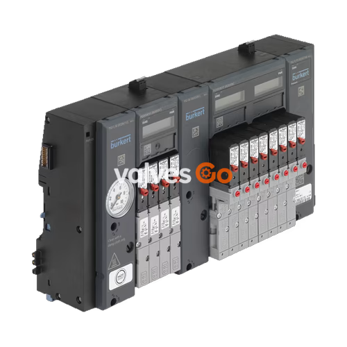
BURKERT 20120692 Type 8647 AirLINE SP is a modular electro-pneumatic automation system designed for direct backplane integration into the Siemens SIMATIC ET 200SP distributed peripheral architecture. Configured with a 24-valve bank capacity at an 11 mm station pitch, this assembly integrates 3/2-way and 5/2-way pilot solenoid valves to operate process valves, pneumatic cylinders, and single- or double-acting pneumatic actuators. The system includes an AirLINE Quick cabinet floor adaptation plate machined from stainless steel (VA), which routes pneumatic pressure supply, exhaust lines, and D6 working connections through the control cabinet base plate to eliminate external bulkheads.
Hardware revision REV.2 incorporates blue release rings on the push-in connectors, a wavy geometric channel arrangement on the working ports, and standardized pneumatic flange profiles (FM20) across single and double valve bodies. Pneumatic safety features include integrated check valves in exhaust ducts 3 (R) and 5 (S) to block back pressure accumulation during simultaneous exhaust, alongside an integrated pneumatic HotSwap shutoff mechanism in supply duct 1 (P). The HotSwap check valve isolates air pressure when a pilot valve is unbolted, permitting live valve servicing under full system operating pressure without process interruption.
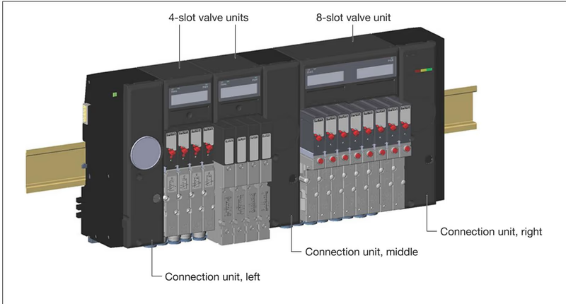
Type 8647 combines Siemens electrical peripheral components with Bürkert fluid technology into a unified terminal rail assembly. The assembly consists of two primary module groups: supply connection units and working valve units.
| Module Designation | Ident Number | Slot Count | Width [mm] | Compatible Valve Types | EVS Option |
|---|---|---|---|---|---|
| PSU-L | 285088 | — | 44 | Supply / Exhaust Left | No |
| PSU-M | 285091 | — | 33 | Intermediate Supply | No |
| PSU-R | 285092 | — | 44 | Exhaust / Terminating Right | No |
| PQ4VS4 | 284935 | 4 | 44 | Type 6524 3/2-way / Type 6525 5/2-way | No |
| PQ8VS4 | 284936 | 4 | 44 | Type 6524 2x3/2-way / Type 0460 | No |
| PQ8VS8 | 283166 | 8 | 88 | Type 6524 3/2-way / Type 6525 5/2-way | No |
| PQ16VS8 | 284806 | 8 | 88 | Type 6524 2x3/2-way / Type 0460 | No |
Burkert 20120692 utilizes the AirLINE Quick mounting method. Instead of mounting the standard DIN rail directly to the control cabinet back wall, the valve island secures to the cabinet floor via a stainless steel floor adapter plate. The adapter plate supports the entire assembly, including the standard rail and all attached Siemens ET 200SP modules.
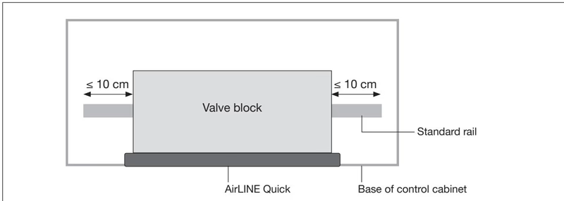
Installation requires a rectangular cutout on the base plate of the control cabinet. The perimeter must be deburred before mounting to prevent cutting the elastomer sealing element.
Installation Limits with AirLINE Quick
When mounting via AirLINE Quick, the projection of the standard rail beyond the valve block must not exceed 10 cm on either side. Only short Siemens BaseUnits can be installed on the rail. Combination of AirLINE Quick with SIMATIC ET 200SP HA is not possible due to profile rail geometry.
If removing or remounting on a DIN rail, all fastening screws must be turned counter-clockwise completely before tilting the block upward. When mounted inside an enclosure, maintain a minimum clearance of 5 cm (8 cm if EVS terminals are wired) between the top of the valve island and adjacent components to permit dissipation of thermal exhaust and access to releases.
The pneumatic interfaces on the 20120692 assembly are located on the connection blocks and beneath the pneumatic base sub-modules via the stainless steel floor plate.
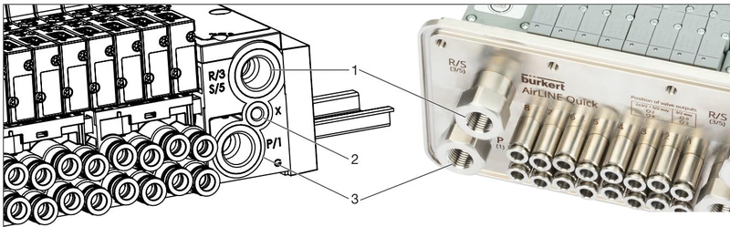
| Port Number | Marking | Function | Thread / Dimension | Recommended Torque [Nm] | Max Torque [Nm] |
|---|---|---|---|---|---|
| 1 | P / 1 | Primary Compressed Air Supply | G 1/4 | 4 to 7 | 20 |
| 3 / 5 | R/3, S/5 | Exhaust Ducts (R and S) | G 1/4 | 4 to 7 | 20 |
| 2 | X | Auxiliary Pilot Air (EXT) / Pilot Exhaust (INT) | M5 | 1.0 to 1.2 | 3 |
| 2, 4 | Bottom | Actuator Working Lines | D6 push-in | 1.75 to 2.25 (M7) | 4 |
Port Connection Verification
Check and verify port assignments 1 (P) and 3/5 (R/S) before charging the line. Ports 1 and 3/5 must never be interchanged under any circumstances, as reverse pressurization will cause uncontrolled actuator movements and structural damage.
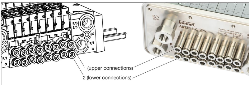
In standard 3/2-way single valve operation (Type 6524), working air discharges through lower port 2 (port 4 remains unused). In 5/2-way (Type 6525) or 2x3/2-way (Type 6524 double valve) configurations, upper port 2 and lower port 4 operate alternately as working outlets.
Exhaust channels 3 (R) and 5 (S) integrate spring-loaded check valves. In multi-valve manifolds, simultaneous venting of large actuators can generate brief pressure spikes in shared exhaust corridors. The integrated non-return valves isolate individual working paths, eliminating unwanted pilot flapper unseating and preventing unintended actuator displacement during safety stops.
Ident number 20120692 features pneumatic HotSwap shutoff seats in port 1 (P). When a pilot valve is unbolted from the pneumatic sub-base, an internal valve seat automatically seals the supply air port for that specific station, retaining full system line pressure (up to 10 bar) across all remaining 23 valve slots.
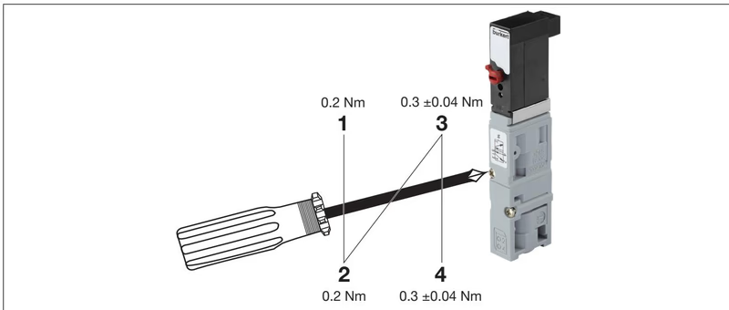
HotSwap Servicing Rules
When unseating a valve under pressure, a brief burst of air escapes until the internal shutoff mechanism seals the differential opening. Operators must wear safety glasses. Do not loosen more than one valve simultaneously from the same pneumatic base module.
Hardware Revision Compatibility
REV.1 and REV.2 single valves possess distinct flange profiles and channel arrangements. Replace REV.2 valves only with REV.2 spare valves. Mixing REV.1 single valves onto REV.2 pneumatic sub-bases will result in seal failure.
Type 8647 connects directly to the backplane communication bus of the Siemens SIMATIC ET 200SP system. Electrical contacts for digital control, module supply, and bus logic engage automatically when the valve terminal is snapped into place against the left-hand Siemens BaseUnit.
Configuration is executed through Siemens TIA Portal (V13 or higher), SIMATIC STEP 7 (V5.5 SP4 or higher), or SIMATIC PCS 7 (V9.0 SP2 or higher). Configuration files are supplied as GSDML (PROFINET), GSD (PROFIBUS DP), HSP (Hardware Support Package HSP0225 / HSP2105), or HUP (Hardware Update Package for PCS 7).

Each valve module provides local optical feedback:
Each electronic base module records switching cycles independently for the pilot valve and the connected field actuator across every channel. Counter warning limits are parameterized via GSDML/HSP or written via SIMATIC STEP 7 runtime data blocks (WRREC/RDREC via data records DS 130 to DS 135). Counters are retained in non-volatile memory.
| Diagnostic Code Hex (Dec) | Alarm Text | Underlying Cause | Corrective Action |
|---|---|---|---|
| 0x09 (9) | Error | General internal hardware fault | Check mechanical seating; replace module |
| 0x10 (16) | Parameterization error | Invalid configuration parameters | Check TIA Portal module slot mapping |
| 0x11 (17) | No supply voltage | Supply voltage L+ below 21.6 V DC | Verify incoming 24 V DC power bus |
| 0x1F (31) | Component unavailable | Firmware update executing | Await completion of update download |
| 0x02F0 (752) | Pilot valve SCC limit | Pilot valve cycle threshold reached | Replace pilot valve; reset DS 132 bit |
| 0x02F1 (753) | Actuator SCC limit | Field process valve cycle limit reached | Service field actuator; reset counter |
| 0x02F3 (755) | Pilot valve: Wire break | Open circuit or unseated coil terminal | Check coil connection or seat cover |
| 0x02F4 (756) | Pilot valve: Short circuit | Coil short circuit or terminal bridge | Clear short circuit; resettable fuse resets |
| Technical Parameter | Specification / Limit |
|---|---|
| Operating Control Medium | Dry compressed air (oiled or unoiled), neutral inert gases |
| Compressed Air Quality | ISO 8573-1:2010 Class 7.4.4 (max. particle size 5 µm) |
| Operating Pressure Range | 2.5 bar to 10 bar (without auxiliary pilot air) |
| Flow Rate (QnN value) | 300 l/min (reduced by approx. 20% on REV.2 HotSwap sub-bases) |
| Medium Temperature | 0 °C to +50 °C |
| Operating Ambient Temperature | 0 °C to +55 °C |
| Relative Humidity | 75% average, 85% maximum (non-condensing) |
| Atmospheric Pressure / Altitude | 80 kPa to 106 kPa (maximum 2000 m above sea level) |
| Housing Materials | Polyamide (PA), Polycarbonate (PC); Valve body: PA / PPS / Aluminum |
| Sealing Material | Nitrile butadiene rubber (NBR) |
| Electrical Protection Class | Class 3 (DIN EN 61140 / VDE 0140); FE functional ground required |
| Cabinet Base Ingress Rating | IP20 base unit (IP65 in closed cabinet; UL Type 4X via AirLINE Quick) |
| Individual Valve Power Consumption | 0.8 W per pilot solenoid (24 V DC) |
Explore similar products in our catalog


