

PN16

BURKERT 20120106 Type 8652 AirLINE is a 24-bank modular valve island with PROFINET S2 redundancy, 48 digital inputs, HotSwap capability, and ATEX/IECEx Zone 2/22 approval.
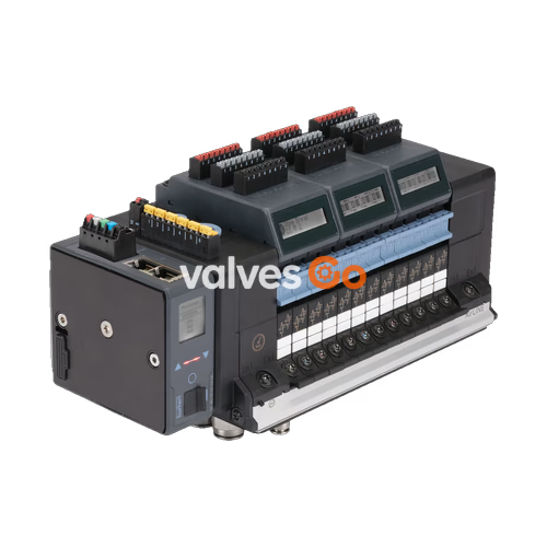
BURKERT 20120106 (Type 8652) AirLINE is a 24-bank modular pneumatic valve island engineered to control pneumatic actuators and process valves within automated process architectures. Built on an aluminium AirLINE Quick (ALQ AL) interface with brass pneumatic connections, this configured assembly incorporates 20 positions of 5/2-way monostable (CF-H) valves, one 3/2-way (CF-C) valve, and three blind plates. It integrates PROFINET S2 system redundancy over dual RJ45 hardware ports and includes six electronic input modules providing 48 digital inputs for direct feedback signal acquisition.
Operating across a nominal pressure span from -1 bar to 10 bar with pilot control pressure between 3 bar and 10 bar, the unit functions in ambient and fluid media temperatures ranging from -10 °C to +55 °C. For process continuity and safety, the assembly integrates pneumatic HotSwap functionality on supply port 1 (P), internal pilot air supply, and integrated check valves in exhaust ducts 3 (R) and 5 (S). Certified versions with order codes PU17 or PX68 comply with ATEX Directive 2014/34/EU, IECEx schemes, NEC classifications, and CCC standard GB/T 3836-2021 for Zone 2 and Zone 22 hazardous locations.
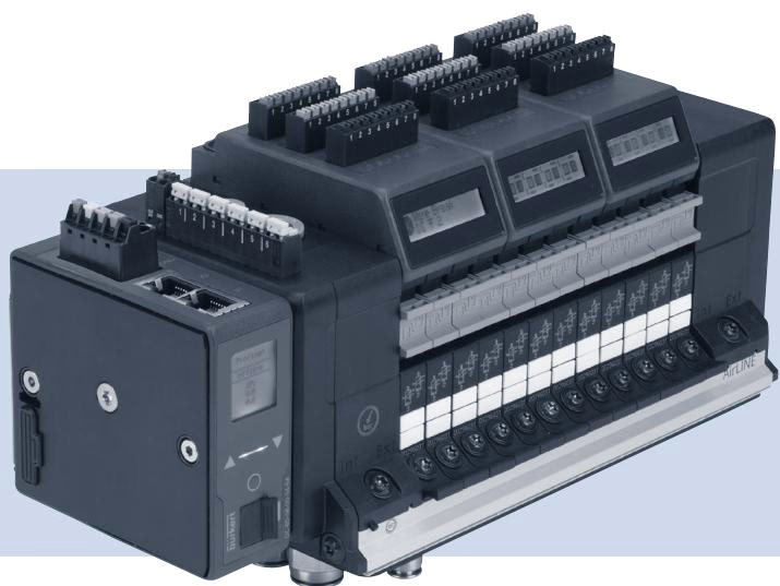
The configured 20120106 valve island combines pneumatic valves, base plate mechanics, and fieldbus communication into a pre-tested assembly.
| Configuration Parameter | Specification Value |
|---|---|
| Type Family | 8652 AirLINE |
| Ident Number (SKU) | 20120106 |
| Total Valve Slices | 24 PCE |
| Valve Positions 1 to 20 | 5/2-way monostable, circuit function H (CF-H) |
| Valve Position 21 | 3/2-way, circuit function C (CF-C) |
| Valve Positions 22 to 24 | Blind plate (reserve positions) |
| Supply Port Connection | D10 push-in, Brass |
| Working Port Connections | D6 push-in, Brass |
| Adapter Plate Interface | AirLINE Quick, Aluminium |
| Pilot Air Configuration | Internal auxiliary pilot air |
| Intermediate Feed | 1 PCE (no additional left, right, or middle external feeds) |
| Check Valves | Integrated check valves in port 3 (R) and port 5 (S) |
| HotSwap Capability | Pneumatic HotSwap integrated on port 1 (P) |
| Communication Protocol | PROFINET S2 (system redundancy) |
| Physical Interface | Dual RJ45 industrial Ethernet ports |
| Digital Inputs | 48 DI total across 6 electrical input modules (8 DI each) |
| Enclosure Rating | IP20 (with mating connectors attached) |
The Type 8652 documentation defines technical abbreviations and system components as follows:
| Term | Definition within System Documentation |
|---|---|
| Actuator / Process Valve | Pneumatic load controlled by the 8652 valve island |
| büS | Bürkert communication bus based on CANopen protocol architecture |
| EVS | External valve shutdown: closes valves in a de-energized state independently of fieldbus master signals; configurable per valve, valve module, or entire block |
| Potentially Explosive Atmosphere | Hazardous industrial areas subject to gas or dust explosion risks |
| Device / Valve Island | AirLINE Type 8652 modular valve island assembly |
| SIA Version | Safety Integrated Architecture version dedicated to certified safety shutdowns (refer to EVS) |
| Pneumatic Valve / Pilot Valve | Pneumatic spool valves integrated into the block, piloted by Type 6164 miniature solenoids |
When deployed under hazardous area supplementary specifications (options PU17 and PX68), Type 8652 must be installed within certified industrial control cabinets meeting structural environmental ratings.
Electrical Isolation in Potentially Explosive Atmospheres
In the presence of an explosive atmosphere, terminal connections for the 24 V DC power supply, SIA, EVS, and digital inputs must only be connected or disconnected when completely de-energized. Fixed cable plugs into terminal blocks must likewise be manipulated only with connected circuits switched off. Disconnecting energized circuits risks incendiary sparking.
Special Conditions for HotSwap Operation
Pneumatic HotSwap enables replacement of individual valve slices under line pressure. Within potentially explosive atmospheres, HotSwap valve removal or insertion is strictly prohibited unless atmospheric testing instruments verify that no explosive gas or dust concentration is present throughout the entire service intervention. Only trained personnel may execute HotSwap procedures.
Type 8652 AirLINE valve islands approved for hazardous zones carry two identification plates: the standard operational rating plate and an Ex compliance plate.
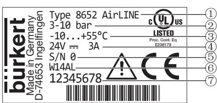
| Position | Parameter Description | Field Data Example |
|---|---|---|
| 1 | Device Type | Type 8652 AirLINE |
| 2 | Pressure Range | 3 to 10 bar (pilot control pressure) |
| 3 | Ambient Temperature Range | -10 °C to +55 °C |
| 4 | Rated Voltage / Current Consumption | 24 V DC / 3 A |
| 5 | Serial Number | S/N (factory assigned) |
| 6 | Manufacturing Code | W14AL (encoded date/batch) |
| 7 | Order Code (Ident Number) | 20120106 (or configured 8-digit ident) |
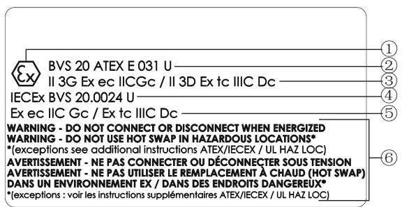
| Position | Description | Approval Data |
|---|---|---|
| 1 | Explosion Protection Logo | Community Ex hexagon mark |
| 2 | ATEX Certificate Number | BVS 20 ATEX E 031 U |
| 3 | ATEX Gas / Dust Marking | II 3G Ex ec IIC Gc / II 3D Ex tc IIIC Dc |
| 4 | IECEx Certificate Number | IECEx BVS 20.0024 U |
| 5 | IECEx Gas / Dust Marking | Ex ec IIC Gc / Ex tc IIIC Dc |
| 6 | Safety Advisory Symbol | Reference to electrical disconnection and HotSwap limits |
| Position | Description | Approval Data |
|---|---|---|
| 1 | US/CA Zone Marking (Gas) | Cl I, ZN 2, AEx ec IIC Gc / Ex ec IIC Gc U |
| 2 | US/CA Zone Marking (Dust) | Cl II, ZN 22, AEx tc IIIC Dc / Ex tc IIIC Dc U |
| 3 | US/CA Division Marking | Cl I, Div 2, Gr A, B, C, D / Cl II, III, Div 2, Gr F, G |
| 4 | ATEX Certificate Number | BVS 20 ATEX E 031 U |
| 5 | Explosion Protection Logo | Community Ex hexagon mark |
| 6 | ATEX Gas / Dust Marking | II 3G Ex ec IIC Gc / II 3D Ex tc IIIC Dc |
| 7 | IECEx Certificate Number | IECEx BVS 20.0024 U |
| 8 | IECEx Gas / Dust Marking | Ex ec IIC Gc / Ex tc IIIC Dc |
| 9 | Safety Advisory Symbol | Reference to electrical disconnection and HotSwap limits |
Every hazardous location shipment includes an auxiliary adhesive warning label: WARNING DO NOT CONNECT OR DISCONNECT WHEN ENERGIZED. If cabinet geometry obscures the primary Ex plate, this warning sticker must be affixed in a clearly visible location on the valve island.
Type 8652 systems comply with DEKRA testing standards (BVS 44809 Bochum) and production quality surveillance by PTB (CE 0102). China Compulsory Certification (CCC) is verified by SITIIAS in compliance with GB/T 3836-2021.
| Operating Parameter | Permissible Value / Criterion |
|---|---|
| Rated Supply Voltage | 24 V DC ±10% |
| Nominal Power | Architecture-dependent |
| Ambient Temperature Range | -10 °C to +55 °C |
| Solenoid Pilot Valves | Type 6164 (acting as pilot operators for Type 6534 main valves) |
| Maximum Number of Valve Slices | 48 valve functions maximum |
| Temperature Class Compliance | T4 limit is maintained at cabinet internal ambient temperatures up to +55 °C |
| AirLINE Quick External Surface Temp | Maximum outer cabinet surface temperature does not exceed 80 °C |
Under BVS 20 ATEX E 031 U and IECEx BVS 20.0024 U, permissible modular variations include combinations of up to 48 valve functions using Type 6534 pneumatic valves, Type 6534 SIA safety variants, external valve shutdown (EVS) modules, digital input electronic slices, and pressure sensor modules. Configurations with fewer than 48 valve functions dissipate less electrical power, resulting in equal or lower operating temperatures.
Explore similar products in our catalog


