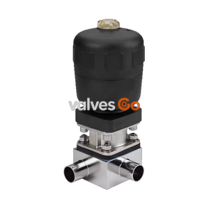
Type 2032

Burkert 20084984 Type 2934 manually operated T-diaphragm valve. Features a DN 25 welded connection, PTFE/EPDM diaphragm, stainless steel block body, and CIP/SIP capability.
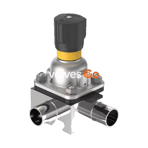
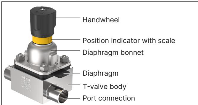
Burkert 20084984 Type 2934 manually operated diaphragm valve consists of a manually operated actuator, a PTFE/EPDM diaphragm, and a stainless steel T-valve body. The manual actuator features a PPS (Polyphenylene sulphide) handwheel and diaphragm bonnet, ensuring reliable use in hygienic or aggressive ambient conditions. The flow-optimised T-valve body with minimum dead space enables high flow values and a wide range of possible applications in the food, beverage, biotechnology, and pharmaceutical industries.
The actuator has a compact, autoclavable design and is equipped with an integrated visual position indicator, a reproducible stroke scale, and an adjustable minimum stroke limiter (closing limiter). The valve is CIP and SIP capable, meeting stringent hygiene requirements.
Explosion Hazard due to Electrostatic Charge
If statically charged devices or persons discharge suddenly, there is an explosion risk in the Ex area. Take appropriate measures to ensure no electrostatic charge can build up. Clean device surfaces only by wiping gently with a damp or antistatic cloth. Ground the actuator and valve body.
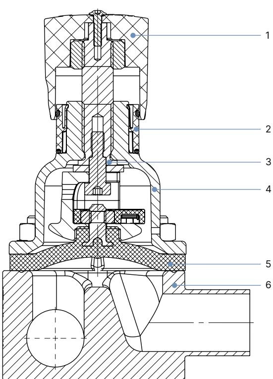
| No. | Element | Material |
|---|---|---|
| 1 | Handwheel | Polyphenylene sulphide (PPS) |
| 2 | Visual position indicator | Polyamide (PA) / Stainless steel 1.4305 |
| 3 | Valve spindle | Stainless steel 1.4305 |
| 4 | Diaphragm bonnet | Polyphenylene sulphide (PPS) |
| 5 | Diaphragm | PTFE with EPDM backing membrane |
| 6 | Valve body | Stainless steel block material 1.4435 (DIN EN 10088) / 316L (ASTM A479) |
By manually overriding the handwheel, the force is transmitted via a spindle and the valve is opened or closed. Turning the handwheel anticlockwise opens the valve, turning it clockwise closes it.
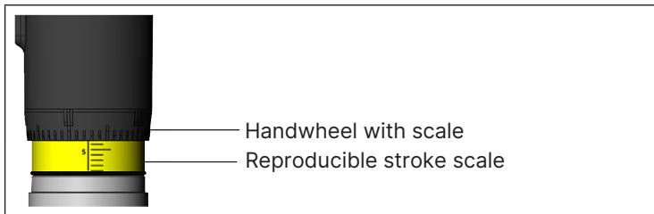
Turning the handwheel counterclockwise reveals the yellow position indicator and the scale marked on it as the valve opens further. The stroke scale shows the relative position of the valve and serves as a fixation point for determining the rotation position.
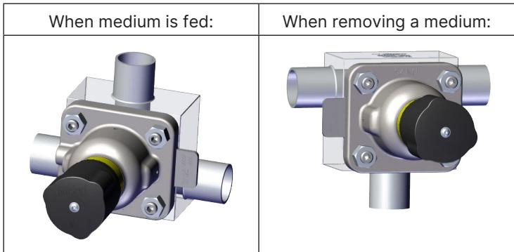
The following installation positions are recommended for the installation of the T-valves in circular pipelines to ensure proper draining and functionality:
Welding Preparations
To prevent damage, dismantle the actuator and diaphragm before welding the valve body into the pipeline. Rotate the handwheel counterclockwise until it comes to a stop (OPEN position), loosen the fastening screws crosswise, and remove the actuator with diaphragm from the valve body.
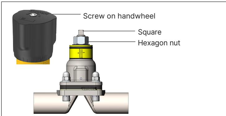
A minimum stroke limit can be set for the Type 2934. This setting also serves as a closing limiter to protect the diaphragm. A hexagon nut is used to do this.
TIP
Do not screw the hexagon nut in the area of the square. Only use the minimum stroke limit in the 0…25 % opening stroke range.
When used in accordance with the operating instructions, the actuator of the diaphragm valve is maintenance-free. After the first steam sterilisation, or when required, retighten the fastening screws crosswise.
Tightening torques for the screws (Diaphragm size 25, PTFE/EPDM):
Maximum permissible tightening torque for the handwheel: Turn the handwheel only until you can feel the valve closing. Do not tighten any further, as the diaphragm may be damaged. For diaphragm size 25 with PTFE at 10 bar static pressure, the maximum tightening torque is 3.5 Nm.
Explore similar products in our catalog