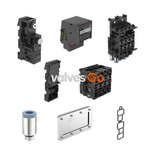
Burkert 20073453 is a Type SVVI left supply unit (connection module) designed for Type 8644 valve islands. It features a 16.5 mm add-on dimension and a G 3/8 pressure port. The module is used for the pneumatic supply and venting of the valve block and serves to fasten the valve block to the standard rail.
Type 8644 is an electrical and pneumatic automation system that has been optimized for use in the control cabinet or switch box. All electronic and pneumatic components are standardized in a continuous system, allowing pneumatic, electric, and electronic modules with different functions to be combined easily.
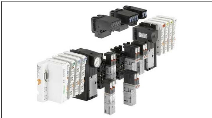
Pneumatic Connection Modules
The valve block is pneumatically supplied and vented via the connection modules. In addition, the valve block is attached to the standard rail via the connection modules.
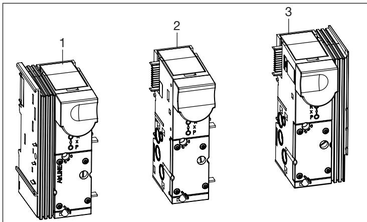
Disassembly of Left Connection Module
WARNING
Risk of injury due to high pressure and escaping medium. Secure the actuators against shifting before working on the modules. Switch off the pressure and vent or empty the lines.
DANGER
Electrostatically sensitive components and units. The units contain electronic components that are susceptible to the effects of electrostatic discharging (ESD). Do not touch electronic components when the supply voltage is connected.
Assembly aids:
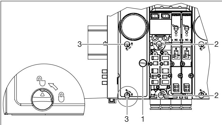
- Slotted screwdriver
- Cross-tip screwdriver
- Carefully rotate the connection module fastening screw anticlockwise with a slotted screwdriver until it comes to a stop.
- Remove the valves from the valve unit on the right side. Loosen the 2 fastening screws of each valve with a cross-tip screwdriver and remove the valves from the valve unit with the flange seal.
- Set the bottom locking element of the valve unit on the right side to the open position with a slotted screwdriver.

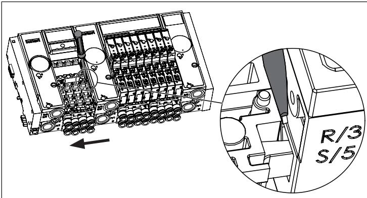
- Unlock the bottom latch hook. Push the left connection module parallel to the standard rail of the locked valve unit away with a slotted screwdriver at the bottom latch hook, until the bottom latch hook unlocks.
WARNING
Major effort required! Do not damage latch hook and electrical contacts!
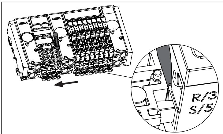
- Set the top locking element of the valve unit on the right side to the open position with a slotted screwdriver.
- Unlock the top latch hook. Push the left connection module parallel to the standard rail of the locked valve unit away with a slotted screwdriver at the top latch hook, until the top latch hook unlocks.

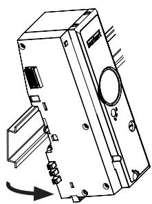
- Next, tilt the connection module slightly upwards and loosen it from the standard rail.

Installation
Assembly aids:
- Standard rail (top hat rail EN 50022 - 35 x 7.5 or 35 x 15)
- Slotted screwdriver
- Installation oil (e.g. CENTOPLEX 2 by KLÜBER LUBRICATION)
Preparatory work:
- Carefully rotate the connection module fastening screw anticlockwise with a slotted screwdriver until it comes to a stop.
- Lightly grease the sealing rings of the pneumatic modules with installation oil.
- Set locking elements to closed position for previously disassembled units.
Installation:
- Place the valve unit to be installed, slightly tilted upwards, on the standard rail and swing it onto the standard rail.
- Position the next unit on the standard rail in the same way.
- Slide units together so that a distance of approx. 0.5 cm is left between the units.
- When sliding together again, make sure that the latch hooks, and then the guide cones and, if applicable, the electrical push-in connector are inserted into the opposite unit.
- Lock units. Always only lock 2 units at the same time.
- Repeat the previous work steps for other units.
Concluding work:
- Conduct a visual inspection: the units must fit parallel to each other, with almost no gaps.
- Fasten the valve block to the standard rail. Carefully rotate the connection module fastening screws clockwise with a slotted screwdriver until they come to a stop.
- Pressure test: apply pressure to the port P (do not exceed the max. pressure for the valves or valve island used here), check tightness.