
Compressed Air Drain Tra...Soft Seal
 Product category
LD and TSF-AT series compressed-air drain traps for automatic condensate removal from air systems.
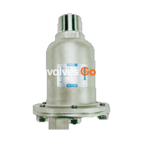
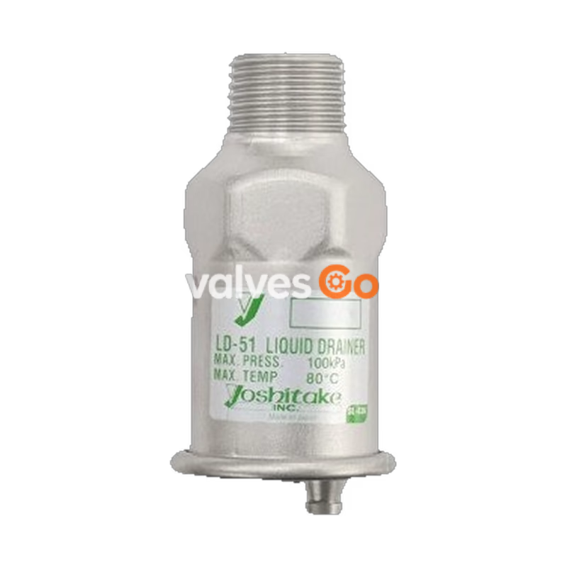
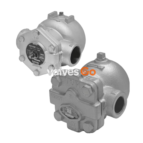
Compare only the points that determine the choice: function or construction, applicable medium, operating range, body material, and connection or nominal size. Open the model page to confirm the full specification.
| Model | Key selection point | Medium | Operating range | Body material | Connection / size |
|---|---|---|---|---|---|
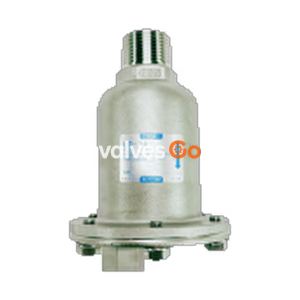
| LD-16 | Gas Trap | Air, Other non-dangerous gas, Hydrogen gas | 0-1.0 MPa 5-90°C | Cast stainless steel | Inlet: JIS R screwed / Outlet: JIS Rc 1/4 screwed; 0-1.0 MPa, Cast stainless steel |
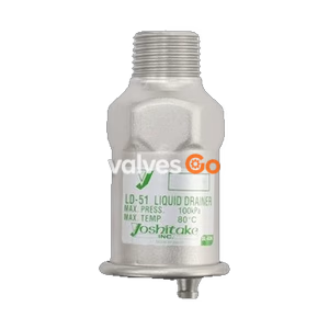
| LD-51 | Gas Trap for Hydrogen and Gas Lines | — | 0-100 kPa 5-80°C | Stainless steel | 0-100 kPa, 15A, Hose joint outlet |
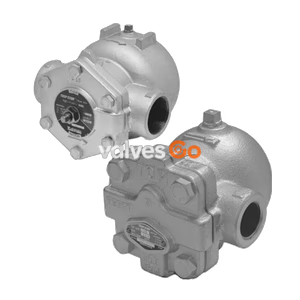
| TSF-11AT | Air Trap | Air, Other non-dangerous fluid / Condensate | TSF-11AT-5: 0.01-0.5 MPa TSF-11AT-10: 0.01-1.0 MPa TSF-11AT-21: 0.01-2.1 MPa 220℃ | Ductile cast iron | JIS Rc screwed / NPT screwed; -5: 0.01-0.5 MPa; -10: 0.01-1.0 MPa; -21: 0.01-2.1 MPa |
| TSF-8AT | Float Type Air Trap (Max 2.1 MPa) | Condensate (Air, Other non-dangerous fluid) | 220℃ | Ductile cast iron | JIS Rc, NPT screwed; -5: 0.01-0.5 MPa; -10: 0.01-1.0 MPa; -21: 0.01-2.1 MPa |
These Yoshitake traps automatically discharge condensate from compressed-air and gas systems while limiting loss of the valuable gas stream. Selection is driven by gas composition, operating pressure, condensate volume, temperature, and whether the installation needs corrosion-resistant wetted materials.
This guide groups local Yoshitake catalogue pages for preliminary engineering review. The model-specific Yoshitake documentation, sizing calculation, materials confirmation, and applicable site requirements control the final order and installation decision.
Open a model page for specifications, connection options and technical documents.